|
|
|
Categories
|
|
Information
|
|
Featured Product
|
|
|
 |
|
|
There are currently no product reviews.
 ;
I'm happy. Good quality. Very helped me with my work..............................
;
This is the second Manual I have ordered from owner-manuals, I give it five stars because it is exactly what I expected given the age of the equipment. So the contents look a bit aged and the pictures a bit grainy, it fulfills my needs and I am glad I can still get hold of them.
;
thank u so much for this manual that was so cheap that i thought it was a scam but i gambled anyway because it was too good of a deal to pass up and behold,the manual has everything and details of everything even the screws and im still amazed and very happy with my manual .so take my word and jump on it before they realize how cheap they selling thier manuals..thank you so much for taking time to read my thoughts
 ;
I do not have very much to say.
The price is quite covenient, delivery was better as promised (about 12 ours, against the specified 24 hours if I remember well), and the quality of the PDF is more than acceptable.
The Service Manual of Sansui R30 itself is also satisfactory: good graphic for schematics and layouts, simple and well structured.
Giovanni Bianchi
;
Happy to find finally a schematic for this amplifier. The schematic is of good quality, the pcb layout is useless: all is black. Never the less, it is very easy to find the components on the board using the schematics.
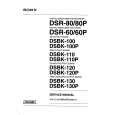
1-1-4. Discharge of flashlight power supply The capacitor which is used as the power supply of flashlight is charged with 200 V to 300 V voltage. Discharge this voltage before starting adjustment in order to protect service engineers from electric shock during adjustment . Discharge procedure 1. Turn OFF the flash switch by pressing the switch S705 on the PK-43 board which turns OFF the flash charging lamp. 2. Fabricate the discharging jig as shown in Fig. 5-1-6 locally by yourself. Connect the discharging jig to the positive (+) and negative (-) terminal of the flash voltage charge capacitor. Allow ten seconds to discharge the voltage.
Capacitor
R
Flash circuit board
R : 1k� 1W (Part code No. 1-215-869-11)
Fig. 5-1-6
1-1-5.
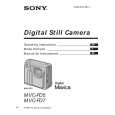
Adjustment remote commander (RM-95 upgraded) To perform adjustment, the adjustment data stored in the non-volatile memory must be rewritten using the adjustment remote commander (RM-95 upgraded). The adjustment remote commander uses the remote commander signal line (LANC) to interactively communicate with the merchandise. The page, address and up/down command data are sent from the adjustment remote commander to the merchandise. In return, the page, address and data are sent to the adjustment remote commander from the merchandise. 1. Using the adjustment remote commander 1) Connect the adjustment remote commander to the LANC terminal (CPC jig). 2) Set the NOR-ADJ (or HOLD) switch of the adjustment remote commander to the �ADJ� (or ON) (service) position. If the adjustment remote commander is correctly connected, the adjustment remote commander�s LED will show the display as shown in Fig. 5-1-7. Bit value discrimination It is necessary to discriminate between the bit values with the data displayed on the adjustment remote commander for all following items. Identify whether the bit value is �1� or �0� with the use of the following diagram.
Display on the adjustment remote commander
Display on the adjustment remote commander 0 1 2 3 4 5 6 A 7 8 9 A (A) B (b) C (C) D (d) E (E) F (F) bit3 or bit7 0 0 0 0 0 0 0 0 1 1 1 1 1 1 1 1
Bit values bit2 or bit6 0 0 0 0 1 1 1 1 0 0 0 0 1 1 1 1 bit1 or bit5 0 0 1 1 0 0 1 1 0 0 1 1 0 0 1 1 bit0 or bit4 0 1 0 1 0 1 0 1 0 1 0 1 0 1 0 1
3)
B
(Example) If �8E� is displayed on the adjustment remote commander, the bit values for bit7 to bit4 are shown in the A column, and the bit values for bit3 to bit0 are shown in the B column.
Address Page bit3 to bit0 discrimination bit7 to bit4 discrimination
Fig. 5-1-7
5-4
|
|
|
> |
|