|
|
|
Categories
|
|
Information
|
|
Featured Product
|
|
|
 |
|
|
There are currently no product reviews.
 ;
Das Service Manual war von der ersten bis zur letzten Seite sehr informativ und hilfreich. Die Darstellung aller Teile war klar und der Text gut lesbar.
Vielen Dank, das war nicht der letzte Download bei ownner-manuals.com.
;
It's a grate service manuals.Have many details and the writing it's so clear.You have all you want in manual,nothing missing,belive me.I'm verry satisfied of this manual.
;
Great scanned service manual
Usefull informations.
I will buy again!
Best Regards
;
The manual describes this product very good. It has the basic things to know and also a more detailed look. Very well made!
;
An excellent document to assist in the repair of my old personal tape player. It includes full circuit diagrams and physical layout drawings and full instructions on disassembly and fault finding.
Well worth the meagre price.
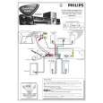
3-1
3-1
DISASSEMBLY INSTRUCTIONS
Dismantling of the Front Panel Assembly
1) Open the DVD Tray by using the Open/Close Button while the Set is ON and disconnect the mains supply after removing the Tray Cover.
Dismantling of the DVD Module
1) Loosen 4 screws "A" to remove the DVD Module as shown in figure 4. 2) Return the set to its upright position and remove the Tray Cover as shown in Figure 3 and close the tray manually by pushing it back in. 3) Loosen 9 screws and remove the Top Cover by lifting the rear portion upwards before sliding it out towards the rear. - 5 screws on the back - 2 screws each on the left & right side 4) Loosen 7 screws & lift up the top edge of Front Panel assembly to free some catches before sliding it out towards the front. - 4 screws on the bottom - 1 screw "E" on the inside as indicated in Figure 8. - 1 screw each on the left & right side
Note: If this is not possible, the DVD Tray has to be open manually.
Take a mini screw driver about 2mm diameter and make a marking 24mm from the tip as shown in figure 2. place the set on its side, insert the mini screw driver till the marking and slide it towards the right as shown in figure 1 until the Tray moves out of the Front Panel.
2mm
A
Repeat
Marking just outside the slot on the rear cabinet
Figure 4
Dismantling of the Power Board 1) Loosen 2 screws "B" on the bottom cover as shown in figure 5.
Figure 1
3) Loosen 4 screws "C" at the top of the Power Board as shown in figure 6
24mm
Figure 2
C
B
Figure 3
Figure 5
Figure 6
|
|
|
> |
|