|
|
|
Categories
|
|
Information
|
|
Featured Product
|
|
|
 |
|
|
There are currently no product reviews.
 ;
Manual was just as described!!! I odered it and in less than a day was able to download it and the text was clear and pages were all complete just as the original manual was. Purcashed this for a friend and they were more than happy. Perfect all around!
 ;
Excellent service and prompt delivery. But it's not a manual - only 4 pages wiring diagrams.
Thanks.
;
The manual I purchased was exactly what I needed to repair my Toshica television. The manual contained schematics and troubleshooting information that was very helpful.
;
Il download del Service Manual JVC HR 4100 non é stato eseguito
;
The Service Manual was just as expected, complete with schematics and I was able to download it in less than an hour after I ordered it. The only problem with these is that the schematics are hard to read due to the small font. I could remedy this by printing them on a larger printer.
3-1
3-1
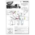
DISASSEMBLY INSTRUCTIONS
Dismantling of the Front Panel Assembly
1) Open the DVD Tray by using the Open/Close Button while the Set is ON and disconnect the mains supply after removing the Tray Cover.
Dismantling of the DVD Module
1) Loosen 4 screws "A" to remove the DVD Module as shown in figure 4. 2) Return the set to its upright position and remove the Tray Cover as shown in Figure 3 and close the tray manually by pushing it back in. 3) Loosen 9 screws and remove the Top Cover by lifting the rear portion upwards before sliding it out towards the rear. - 5 screws on the back - 2 screws each on the left & right side 4) Loosen 7 screws & lift up the top edge of Front Panel assembly to free some catches before sliding it out towards the front. - 4 screws on the bottom - 1 screw "E" on the inside as indicated in Figure 8. - 1 screw each on the left & right side
Note: If this is not possible, the DVD Tray has to be open manually.
Take a mini screw driver about 2mm diameter and make a marking 24mm from the tip as shown in figure 2. place the set on its side, insert the mini screw driver till the marking and slide it towards the right as shown in figure 1 until the Tray moves out of the Front Panel.
2mm
A
Repeat
Marking just outside the slot on the rear cabinet
Figure 4
Dismantling of the Power Board 1) Loosen 2 screws "B" on the bottom cover as shown in figure 5.
Figure 1
3) Loosen 4 screws "C" at the top of the Power Board as shown in figure 6
24mm
Figure 2
C
B
Figure 3
Figure 5
Figure 6
|
|
|
> |
|