|
|
|
Categories
|
|
Information
|
|
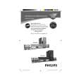
Featured Product
|
|
|
 |
|
|
There are currently no product reviews.
 ;
y'm hapy for this shoping . Estoy feliz por esta compra , ahora puedo reparar mi equipo de audio que AMO . And very good price for this manual . Thank yuo .
;
Perfect manual, perfect service. Easy reading. Thanks a lot
;
Very good quality download here. Great hard to find manuals at a reasonable price.
 ;
I had a problem with the mains transformer, I did not know the voltages on the secondary, this manual helped me to solve this problem, thanks for the manual!
;
Great manual, great quality copy, complete parts reference and scematics, Thank you
2-1
2-1
DISMANTLING INSTRUCTIONS
Dismantling of the Front Panel assembly 1) Loosen the 9 screws to dismantle the Top Cover (pos 252) - 2 screws on each side - 5 screws on the Rear Panel (pos 251). 2) Loosen 5 screws A and 8 catches C1 to slide the Front Panel assembly (pos 101, 102, 103, etc) as per figure 1. Note: To remove the Source / Volume control pc board (pos 1105B) 2 nuts hidden below the control knob assembly (pos 133, 134 and 135) must first be removed. 3) Loosen bracket (pos 254) by turning a catch, sliding towards the outside and lifting it upwards as per figure 5. Dismantling the Tuner, Mains and AV boards 1) Loosen 3 screws D and 2 catches C2 on the Rear panel (pos 251) to remove the Tuner board assemby (pos 1101) as pe figure 3. 2) Loosen 1 screws E and 2 catches C3 to unslot the Mains board (pos 1102-A) out of the Rear panel as per figure 4. 4) Loosen 7 screws F and 2 C5 to separate Rear Plate assembly (pos 251 + 227) from the Bottom plate as per figure 3. 5) Uncatch C4 to remove the AV board (pos 1104) from the Bottom & Rear Plate assembly (pos 251 + 227) as per figure 5.
C1
C1
C1
C1
A A
C1
A
C1
A
C1
Figure 1
A
C1
Figure 3
2 1 Turn up the lever, slide the bracket as shown and lift out of the bottom chassis.
Hints for re-assembly of Top Cover Due to appearance design the Top cover (pos 252) is sandwiched between the Front panel (pos 101) and the 2 side covers (pos 102 & 103), this make it necessary to remove the 2 side covers before re-assembly of Top cover. 2) Insert the screw driver into slot (as shown in figure 2) and push the tip outwards to release the side cover catch. The side cover can be pull outwards as soon as the top catch is released. Dismantling the 5DTC Module 1) Loosen 1 screws E and 2 catches C3 to remove the Mains board as per figure 4. 2) Loosen bracket (pos 254) by turning a catch, sliding towards the outside and lifting it upwards as per figure 5. 3) Loosen 3 screws G, lift up the 5DTC Module's (pos 1103A) rear and pull the module out towards the rear as per figure 6. Figure 4 1) To remove the side cover use a small screw driver with marking 16mm from the tip end.
C4
Figure 5
G G
Figure 2 Figure 6
|
|
|
> |
|