|
|
|
Categories
|
|
Information
|
|
Featured Product
|
|
|
 |
|
|
There are currently no product reviews.
 ;
It was magic after so many years to still be able to source this info. It was equally amazing to return my Pioneer receiver to it near new sound quality AFTER NEARLY 30 YEARS! Thank you for this ability!
;
Very quick and easy website to use and fast download of manual, quality of manual is excellent and will be pleased to use this service again in the future, thanks so much!
 ;
Easy and secure way to get a complete service manual of a vintage hifi component. Only some parts of the print copy are dificult to read. Nice price!
;
The manual is an excellent reproduction with complete schematics, made troubleshooting and repair a simple process.
;
Up to now you are the BEST! Prompt-efficient and so reasonable ! I have been after SONY service manual for quite some time !Thank you very much ! I can recomend your service to
all my collegagues ! V.Bergfield .
1-A. Preliminary/Final Checking and Alignment of Tape Path
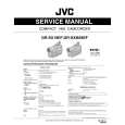
Purpose: To make sure that the tape path is well stabilized. Symptom of Misalignment: If the tape path is unstable, the tape will be damaged. Note: Do not use an Alignment Tape for this procedure. If the unit is not correctly aligned, the tape may be damaged. 1. Playback a blank cassette tape and check to see that the tape runs without creasing at Guide Rollers [2] and [3], and at points A and B on the lead surface. (Refer to Fig. M3 and M4.) 2. If creasing is apparent, align the height of the guide rollers by turning the top of Guide Rollers [2] and [3] with a Guide Roller Adj. Screwdriver. (Refer to Fig. M3 and M5.)
Guide Roller [2] Guide Roller [3]
3. Check to see that the tape runs without creasing at Take-up Guide Post [4] or without snaking between Guide Roller [3] and AC Head. (Fig. M3 and M5) 4. If creasing or snaking is apparent, adjust the Tilt Adj. Screw of the AC Head. (Fig. M6)
Azimuth Adj. Screw
AC Head X-Value Adj. Screwdriver
Tilt Adj. Screw
Fig. M6
1-B. X Value Alignment
Purpose: To align the Horizontal Position of the Audio/Control/ Erase Head. Symptom of Misalignment: If the Horizontal Position of the Audio/Control/Erase Head is not properly aligned, maximum envelope cannot be obtained at the Neutral position of the Tracking Control Circuit. Fig. M3 1. Connect the oscilloscope to TP301 (C-PB) and TP503 (CTL) on the Main CBA. Use TP504 (RFSW) as a trigger. 2. Playback the Gray Scale of the Alignment Tape (FL6NS8) and confirm that the PB FM signal is present. 3. Set the Tracking Control Circuit to the center position by pressing "VCR" button and "KCH" button on the remote control unit then pressing "PLAY" button on the unit. (Refer to note on bottom of page 2-3-4.) 4. Use the X-Value Adj. Screwdriver so that the PB FM signal at TP301 (C-PB) is maximum. (Fig. M6) 5. Press "KCH" button on the remote control unit until the CTL waveform has shifted by approx. +2msec. Make sure that the envelope is simply attenuated (shrinks in height) during this process so that you will know the envelope has been at its peak.
ACE Head
A
B Take-up Guide Post [4]
Lead Surface of Cylinder
Tape
Fig. M4
Correct
Guide Roller Tape
Incorrect
Take-up Guide Post Tape
Fig. M5 2-3-3 E9015MA
|
|
|
> |
|