|
|
|
Categories
|
|
Information
|
|
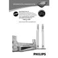
Featured Product
|
|
|
 |
|
|
There are currently no product reviews.
 ;
Wow very wonderful and clear!!!! I will always trust them
;
Providing the manual works fine, quickly and without any problems for an acceptable price. After printing the service manual it took me only a short time to repair my carradio from Clarion. Thank You! Greetings from Heiko
;
I was searching a way to modify the original phono-in entry (for connection of vynil disc player, with RIAA equalization) to a line-in entry (for connection of modern analog entries, eg. ipod, mp3player).
This service manual gave me the correct hints.
It contains very useful infos for repairing and modifing the hi-fi, such as disassembling instructions, block diagrams, schematic diagrams, PCB prints, replacement parts list.
Very good!
;
Great Job!!! clear and efficient as always!!
it is really nice to have peple that are doing such a good work!!!!!
;
I must admit, I was very skeptical... $4.99 for a 74 page service manual. I've seen some very poorly scanned manuals on the Internet, but this one is VERY good quality! Even when zooming into 500%. Great Deal!
2-1
2-1
DISMANTLING INSTRUCTIONS
Dismantling of the Front Panel assembly 1) Loosen the 9 screws to dismantle the Top Cover (pos 252) - 2 screws on each side - 5 screws on the Rear Panel (pos 251). 2) Loosen 5 screws A and 8 catches C1 to slide the Front Panel assembly (pos 101, 102, 103, etc) as per figure 1. Note: To remove the Source / Volume control pc board (pos 1105B) 2 nuts hidden below the control knob assembly (pos 133, 134 and 135) must first be removed. 3) Loosen bracket (pos 254) by turning a catch, sliding towards the outside and lifting it upwards as per figure 5.
D
Dismantling the Tuner, Mains and AV boards 1) Loosen 3 screws D and 2 catches C2 on the Rear panel (pos 251) to remove the Tuner board assemby (pos 1101) as pe figure 3. 2) Loosen 1 screws E and 2 catches C3 to unslot the Mains board (pos 1102-A) out of the Rear panel as per figure 4. 4) Loosen 8 screws F (7 screws for non-Scart version) and 2 catches C5 to separate Rear Plate assembly (pos 251) from the Bottom plate assembly (pos 227) as per figure 3. 5) Uncatch C4 to remove the AV board (pos 1104) from the Bottom Plate assembly (pos 227) as per figure 5.
C1
C1
C1
C1
A A
C1
A
C1
C5
C2 C5
A
C1
Figure 1
A
F
C1
Figure 3
F
2 1
Hints for re-assembly of Top Cover Due to appearance design the Top cover (pos 252) is sandwiched between the Front panel (pos 101) and the 2 side covers (pos 102 & 103), this make it necessary to remove the 2 side covers before re-assembly of Top cover. 1) To remove the side cover use a small screw driver with marking 16mm from the tip end. 2) Insert the screw driver into slot (as shown in figure 2) and push the tip outwards to release the side cover catch. The side cover can be pull outwards as soon as the top catch is released.
C4
Turn up the lever, slide the bracket as shown and lift out of the bottom chassis.
Figure 4 Figure 5
Dismantling the Supply & Power Amplifier boards 1) Loosen 2 screws B mounting the Supply board's (pos 1102-B) heatsink to the Bottom Plate (pos 227) as per figure 6. Note: During re-assembly care must be taken to ensure the Mains Transformer wires to the Supply board is routed properly below the board. 2) Loosen 4 screws C to dismantle the Power Amplifier board (pos 1102-D) from the Bottom Plate as per figure 6. Figure 2 Figure 6
|
|
|
> |
|