|
|
|
Categories
|
|
Information
|
|
Featured Product
|
|
|
 |
|
|
There are currently no product reviews.
 ;
Thanks for offering this item at such a good price. Proved handy in identifying the part I was looking for my set.
Thanks again.
;
This is the original manufacturers service manual, with detailed info on the circit boards, explosion drawings of all parts in assembly order, and tuning instructions. The only thing missing is the information on the dimensions of the various drive belts. mail me if you need them. gcrossman_at_aol.com
;
Ordered service manuel for a hard to find plasma tv - your company made it easy to find and purchase - I will use you again
Thanks for your help
 ;
This is a high quality manual with clear schematic and components layout diagrams ; with service procedure included.
;
This service manual for the Kenwood KT-990D was reproduced really well ,is very legible and manual is complete.Combined with the low price paid,in the future,I will be checking Owner-Manuals.com any time I need a manual.
7. INITIAL SETTING OF ADJUSTMENT VALUE
Note: Mode which sets the adjustment results recorded in the non-volatile memory to the initial setting value. However the results of the temperature compensation offset adjustment will not change to the initial setting value. If initial setting is performed, perform all adjustments again excluding the temperature compensation offset adjustment. For details of the initial setting, refer to �4. Precautions for Adjustments� and execute the initial setting before the adjustment as required.
9. TEMPERATURE COMPENSATION OFFSET ADJUSTMENT
Save the temperature data at that time in the non-volatile memory as 25 �C reference data.
Note: 1. Usually, do not perform this adjustment. 2. Perform this adjustment in an ambient temperature of 22 �C to 28 �C. Perform it immediately after the power is turned on when the internal temperature of the unit is the same as the ambient temperature of 22 �C to 28 �C. 3. When D101 has been replaced, perform this adjustment after the temperature of this part has become the ambient temperature.
Setting Procedure: 1. Turn the [l AMS L] (MD) knob to display �ADJ CLEAR� (C28). 2. Press the [YES] button. �Complete!� will be displayed momentarily and initial setting will be executed, after which �ADJ CLEAR� (C28) will be displayed.
8. RECORDING AND DISPLAYING THE IOP INFORMATION
The Iop data can be recorded in the non-volatile memory. The Iop value on the optical pick-up label and the Iop value after the adjustment will be recorded. Recording these data eliminates the need to read the label on the optical pick-up. Recording Procedure: 1. Turn the [ l AMS L ] (MD) knob to display �Iop Write� (C05), and press the [YES] button. 2. The display becomes �Ref=@@@.@� (@ is an arbitrary number) and the numbers which can be changed will blink. 3. Input the Iop value on the optical pick-up label. To select the number : Turn the [l AMS L] (MD) knob. To select the digit : Press the [ l AMS L] (MD) knob 4. When the [YES] button is pressed, the display becomes �Measu=@@@.@� (@ is an arbitrary number). 5. As the adjustment results are recorded for the 4 value. Leave it as it is and press the [YES] button. 6. �Complete!� will be displayed momentarily. The value will be recorded in the non-volatile memory and the display will become �Iop Write� (C05). Display Procedure: 1. Turn the [ l AMS L ] (MD) knob to display �Iop Read� (C26). 2. �@@.@/##.#� is displayed and the recorded contents are displayed. @@.@ indicates the Iop value on the optical pick-up label. ##.# indicates the Iop value after adjustment 3. To end, press the [l AMS L] (MD) button or [MENU/NO] button to display �Iop Read� (C26).
Adjusting Procedure: 1. Turn the [ l AMS L ] (MD) knob to display �TEMP ADJUST� (C03). 2. Press the [YES] button to select the �TEMP ADJUST� mode. 3. �TEMP = [OK� and the current temperature data will be displayed. 4. To save the data, press the [YES] button. When not saving the data, press the [MENU/NO] button. 5. When the [YES] button is pressed, �TEMP = SAVE� will be displayed and turned back to �TEMP ADJUST� (C03) display then. When the [MENU/NO] button is pressed, �TEMP ADJUST� (C03) will be displayed immediately. Specified Value: The �TEMP = � should be within �E0 - EF�, �F0 - FF�, �00 0F�, �10 - 1F� and �20 - 2F�.
10. LASER POWER ADJUSTMENT
Check the Iop value of the optical pick-up before adjustments. (Refer to 8. Recording and Displaying Iop Information) Connection:
laser power meter
Optical pick-up objective lens
digital voltmeter BD (MD) board CN105 pin 1 (I +3 V) CN105 pin 2 (IOP)
+ �
Adjusting Procedure: 1. Set the laser power meter on the objective lens of the optical pick-up. (When it cannot be set properly, press the m (MD) button or M (MD) button to move the optical pick-up) Connect the digital voltmeter to CN105 pin 1 (I+3V) and CN105pin 2 (IOP) on the BD (MD) board. 2. Turn the [ l AMS L ] (MD) knob to display �LDPWR ADJUST� (C04). (Laser power : For adjustment) 3. Press the [YES] button once to display �LD 0.9 mW $ �. 4. Turn the [l AMS L ] (MD) knob so that the reading of the laser power meter becomes 0.85 to 0.91 mW. Press the [YES] button after setting the range knob of the laser power meter, and save the adjustment results. (�LD SAVE $ � will be displayed for a moment) 5. Then �LD 8.4 mW $ � will be displayed.
38
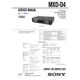 $4.99 MXDD4 SONY
Owner's Manual Complete owner's manual in digital format. The manual will be available for download as PDF file aft…
|
|
|
> |
|