|
|
|
Categories
|
|
Information
|
|
Featured Product
|
|
|
 |
|
|
There are currently no product reviews.
 ;
I was having a hard time finding the problem with this Mackie 1604 unit. I didn't have a schematic. Went looking on the web and found your site and the price was more then reasonable. Ordered it and within the hour had the manual and within 15 minutes had the unit fixed. Best $4.99 I ever spent. Thank you.
Doug
;
This is a service manual in every sense of the word ( French and German versions of the text are included, as well as English..)
There are explanations of the mechanical and electrical functions, plenty of mechanical drawings, and the needed schematics. The quality of the scanning is excellent - all the component values are clearly legible - and very usefully there are pcb component layouts, so you can find a component on the schematic, and then very quicky pinpoint its physical location on the relevant pcb.
I cannot see how I can give this manual any less than the maximum 5 stars! Great value for money, which will pay for itself immediately. Excellent all round!
;
the manual is great and especially hard to find... thanks for the great service and having a hard to find manuel_
;
Please tell us what you think and share your opinions with others. Be sure to focus your comments on the product. You will receive $2.50 of store credit for Your review.
;
hat alles sehr gut geklappt. Das Servicemaual ist gut zu verwenden. Die Pläne und Schrift
ist klar und leserlich. Außerdem preiswert. Grüße an alle Hifi-Bastler
(5)
1) 2) 3) 4)
Processing Tray Upper Cover
Remove the front cover. (See (2).) Remove the rear cover. (See (3).) Remove the upper cover. (See (4).) Disconnect the connector [1] and remove the screw [2].
(7)
1) 2) 3) 4) 5)
Removing the Saddle Guide
Remove the delivery tray. (See (1).) Remove the front cover. (See (2).) Remove the rear cover. (See (3).) Free the delivery tray support plate (front) [1] and the delivery tray support plate (rear) [2] to the outside from the rail grooves. Remove the four screws [3].
[3] [2]
[3]
[1]
[3]
[3]
[2]
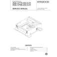
6) Shift the side guide [4] lightly to the front, and free the engagement of the paper surface detecting lever (rear) [5]; then, detach the side guide [4].
[1]
5) While lifting the processing tray cover [3], disconnect the connector [4], then remove the processing tray upper cover [3].
[5]
[3]
[4]
NOTE: Be sure to mount the side guide after securely fitting the paper surface detecting lever (rear) [5] in the groove of the paper surface detecting lever (middle) [6]. After completion of mounting, push the paper surface detecting lever several times to make sure that side guide is mounted securely.
[4]
(6)
1) 2) 3)
Upper Right Cover, Middle Right Cover
Remove the front cover. (See (2).) Remove the rear cover. (See (3).) Open the upper cover, then remove the upper right cover and the middle right cover.
[5]
1
[6]
[5]
[6]
2
MX-FNX2/AR-PN1/MX-RBX1 DISASSEMBLY AND ASSEMBLY 6 � 2
|
|
|
> |
|