|
|
|
Categories
|
|
Information
|
|
Featured Product
|
|
|
 |
|
|
There are currently no product reviews.
 ;
Great Manual. It was exactly what I was looking for
;
I am really satisfied. It was ceap, easy and quick. Te owner manual is a full service book. I got what I expected. Thx
;
The service was good but it just a little late for the download. It seems that it needs to clear the payment but the payment was settled by paypal. As far as my concern, it should be able to download after the confirmation of sold.
;
Great quality manual, fast service, excellent seller... Thanks !!!
;
Great manual and fast service. Download was possible after a few hours.
MX-G500
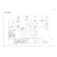
Disassembly method
Removing the metal cover (See Fig.1)
1. Remove the three screws A attaching the metal cover on the back of the body. 2. Remove the six screws B attaching the metal cover on the both sides of the body. 3. Remove the metal cover from the body by lifting the rear part of the cover. ONE POINT How to eject the CD tray (see fig.2) Although it will end if the OPEN/CLOSE button is pushed when a power supply can be taken, when that is not right, CD tray will be opened manually. Turn the loading pulley gear at the bottom of the CD changer unit as shown in Fig.2 and draw the CD tray toward the front.
Metal cover
A
B
(both sides)
Fig.1
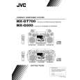
Loading pulley gear (See <CD changer unit>fig.1)
Removing the CD Tray fitting (See Fig. 3)
Prior to performing the following procedure, eject the CD tray. 1. After drawing the lower part of the tray fitting toward the front, remove the five claws. Then, while moving the tray fitting upward, remove it.
CD tray fitting
Fig.2
Joint
Removing the CD changer unit (See Fig.4 to 7)
Prior to performing the following procedure, remove the metal cover. 1. Remove the card wire attached to CD changer unit on the adhesion tape.
Claw
2. Disconnect the card wire from the connector CW107 on the CD servo board. 3. Disconnect the harness from the connector RCW6 on the main board and CW105 on the CD servo board. 4. Remove the two screws C attaching the CD changer unit to the rear panel. 5. Remove the two screws D attaching the CD changer unit to the both side of front panel assembly. 6. Draw the CD changer unit upward from behind while pulling the rear panel outward.
Adhesion tape
Fig.3
CD changer unit
Card wire
Fig.4 1-5
 $4.99 MXG500 JVC
Owner's Manual Complete owner's manual in digital format. The manual will be available for download as PDF file aft…  $4.99 MX-G500 JVC
Parts Catalog Parts Catalog only. It's available in PDF format. Useful, if Your equipment is broken and You need t…
|
|
|
> |
|