|
|
|
Categories
|
|
Information
|
|
Featured Product
|
|
|
 |
|
|
There are currently no product reviews.
 ;
Easy to order the manual. Good quality and fast delivery.
;
The Service Manual for Sansui AU-9500 was very helpfull, in complete and in good printable condition.
Thanks.
;
Dear Sir,
Document is original service document of sharp. I had a problem with the door contacts. Fuses where blown. With the manual in a few minuts is was clear what the problem was.
Manual was of great help.
With kind regards,
Martie Verhoeven
The Netherlands.
 ;
The scan is clear and well readable with very few weaker spots, usually on black background with white letters, but with enough zoom those spots can be read.
Printout is clear, the manual is complete and has all pages scanned.
I would give 5 stars, except that it is not in color, and the schematic and PCB pages are scanned on multiple pages. The document is locked (except printing) so the pages can not be extracted to compose them together for printing on the large plotter
It is worth the price tag.
;
let's say first that i do not need to have a credit for my opinion, i am a retired sparkie and i voluteerd to fix an electronic device for a local "Youthgroup",as no diagram was present i checked the "net" and gambled on this site and paying some fee via PayPall, i was gladly surprised that the manual arrived as was stated, GOOD SHOW, and best wishes, John
MX-G70
< Cassette mechanism section >
Removing the playback,recording and eraser heads (See Fig.1~3)
1. While shifting the trigger arms seen on the right side of the head mount in the arrow direction,turn the flywheel R in counterclockwise direction until the head mount has gone out with a click (See Fig. 1). 2. When the flywheel R is rotated in counterclockwise direction, the playback / recording & eraser head will be turned in counterclockwise direction from the position in Fig.2 to that in Fig.3. 3. At this position, disconnect the flexible P.C.board (outgoing from the playback head) from the connector CN301 on the head amp. and mechanism control P.C. board. 4. Remove the flexible P.C.board from the chassis base. 5. Remove the spring "a" from behind the playback / recording head. 6. Loosen the reversing azimuth screw retaining the playback head. 7. Take out the playback head from the front of the head mount. 8. The recording and eraser heads should also be removed similarly according to Steps 1~7 above.
Cassette mechanism
Flywheel R
Head mount
Trigger arm (Mechanism A side)
Fig.1
Playback/Recording & eraser head Flexible P.C.board
Spring "a" Trigger arm
Reassembling the playback, recording and eraser heads (See Fig.3)
1. Reassemble the playback head from the front of the head mount to the position as shown in Fig.3. 2. Fix the reversing azimuth screw. 3. Set the spring a from behind the playback head. 4. Attach the flexible P.C.board to the chassis base as shown in Fig.3. 5. The recording and eraser heads should also be reassembled similarly according to Steps 1~4 above.
CN301 Head amplifier & mechanism control P.C. board Flywheel R
Fig.2
(Mechanism A side)
Playback head
Reversing azimuth screw Head mount Flexible P.C.board CN302
Spring "a"
FPC holder
Head amplifier & mechanism control
Fig.3
P.C. board (Mechanism B side)
1-20
 $4.99 MX-G70 JVC
Circuit Diagrams Set of circuit diagrams. The diagrams will be provided as PDF file. The file will be delivered after… 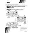 $4.99 MX-G70 JVC
Owner's Manual Complete owner's manual in digital format. The manual will be available for download as PDF file aft…  $4.99 MX-G70 JVC
Parts Catalog Parts Catalog only. It's available in PDF format. Useful, if Your equipment is broken and You need t…
|
|
|
> |
|