|
|
|
Categories
|
|
Information
|
|
Featured Product
|
|
|
 |
|
|
There are currently no product reviews.
 ;
I searched EVERYWHERE looking for the manual/s on this "extinct" amp. Owner-Manuals.com made it available and for nearly nothing. Thanx to them, I can decipher the unknown cables and sort them out. Thanx, Owner-Manuals.com!!
;
Yes thank you i got the file i was after. There was a slight problem in my communication but it all worked out well.
A job well done.
 ;
Great manual...really saved me. The only problem is that I thought I would be able to download it directly when I paid for it but never received the download instructions until the next morning. The board trace pages were somewhat light also: really need to turn up the contrast on the printer before printing them. The schematic page was great; very clear! Well worth the money.
;
I've been in the electronic business for a long time. I used to buy Sam's Photofact for my needs which intailed having to go to the store and paying about $20 for a package of 3 different units so I was forced to buy more than I needed just to get one.
Owner manual is just at your keyboard and the information is almost instantansouly and the cost is very reasonable. Easy to print out if needed or simply read off of the screen. The larger the screen the better for obvious reasons.
;
Very good manual, at a very good price. Received in a timely manner
MX-GT700
Removing the heat sink & amp. board (See Fig.8, 11 and 12)
Prior to performing the following procedure, remove the metal cover and CD changer unit. 1. Disconnect the card wire from the connector ACW1 and the harness from the connector ACW2, ACW5 and ACW6 on the amp. board. 2. Remove the four screws I attaching the heat sink cover to the rear panel. Remove the heat sink cover. 3. Remove the four screws J attaching the heat sink and two screws K attaching the speaker terminal to the rear panel. 4. After moving the heat sink upward, remove the claws. Then pull out the heat sink & amp. board inward. If the voice board is removed at this time, it will be able to work comfortably.
Heat sink cover
Joint2
(Bottom side)
H
Fig.10
Rear panel
I
I
Removing the fan motor (See Fig.8 and 12)
Prior to performing the following procedure, remove the metal cover and heat sink cover.
1. Disconnect the harness from the connector ACW5 on the amp. board. Fig.11
L J
Rear panel
2. Remove the two screws L attaching the fan motor Claws to the rear panel. Heat sink
M N K
Removing the tuner board (See Fig.12 and 13)
Prior to performing the following procedure, remove the metal cover. 1. Disconnect the card wire from the connector CON01 on the tuner board. 2. Remove the two screws M attaching the tuner board to the rear panel.
J
Speaker terminal
O P
Fig.12
Main board CON01 Rear panel
Tuner board
Removing the rear panel
(See Fig.12)
Prior to performing the following procedure, remove the metal cover, CD changer unit, heat sink & amp. board and tuner board. 1. Remove the two screws N, screw O and three screws P attaching the rear panel.
Fig.13
1-7
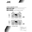 $4.99 MXGT700 JVC
Owner's Manual Complete owner's manual in digital format. The manual will be available for download as PDF file aft…  $4.99 MX-GT700 JVC
Parts Catalog Parts Catalog only. It's available in PDF format. Useful, if Your equipment is broken and You need t…
|
|
|
> |
|