|
|
|
Categories
|
|
Information
|
|
Featured Product
|
|
|
 |
|
|
There are currently no product reviews.
 ;
El producto satisface las necesidades del servicio t
;
This is a good quality scan of the Operation & Maintenance (Service) Manual for the PAL version of this high-band broadcast umatic, BVU-800P
All schematics and lineup procedures appear to be included in this one manual AFAICT.
The file size is just over 113 MB which gives an idea of the quality and number of pages.
All of the schematics, which contain some fairly small print, are easily readable when you zoom into the page.
John Thompson, Newcastle Upon Tyne, England.
;
Good quality, all schematics of few of models. There is also short form of user manual and regulation manual.
;
Perfect copy of the service manual. you can enlarge every page, and it comes up
with all details.
;
It´s very very nice manual with all, what i need. Original in good quality. Very fast business. Very much thanks...
MX-GT98V/MX-GT95V/MX-GT88V MX-GT85V/MX-G78V/MX-G75V
< Cassette mechanism section >
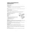
Removing the playback,recording and eraser heads (See Fig.1~3)
1. While shifting the trigger arms seen on the right side of the head mount in the arrow direction,turn the flywheel R in counterclockwise direction until the head mount has gone out with a click (See Fig. 1). 2. When the flywheel R is rotated in counterclockwise direction, the playback / recording & eraser head will be turned in counterclockwise direction from the position in Fig.2 to that in Fig.3. 3. At this position, disconnect the flexible P.C.board (outgoing from the playback head) from the connector CN301 on the head amp. and mechanism control P.C. board. 4. Remove the flexible P.C.board from the chassis base. 5. Remove the spring "a" from behind the playback / recording head. 6. Loosen the reversing azimuth screw retaining the playback head. 7. Take out the playback head from the front of the head mount. 8. The recording and eraser heads should also be removed similarly according to Steps 1~7 above.
Cassette mechanism
Flywheel R
Head mount
Trigger arm (Mechanism A side)
Fig.1
Playback/Recording & eraser head Flexible P.C.board
Spring "a" Trigger arm
Reassembling the playback, recording and eraser heads (See Fig.3)
1. Reassemble the playback head from the front of the head mount to the position as shown in Fig.3. 2. Fix the reversing azimuth screw. 3. Set the spring a from behind the playback head. 4. Attach the flexible P.C.board to the chassis base as shown in Fig.3. 5. The recording and eraser heads should also be reassembled similarly according to Steps 1~4 above.
CN301 Head amplifier & mechanism control P.C. board Flywheel R
Fig.2
(Mechanism A side)
Playback head
Reversing azimuth screw Head mount Flexible P.C.board CN302
Spring "a"
FPC holder
Head amplifier & mechanism control
Fig.3
P.C. board (Mechanism B side)
1-26
|
|
|
> |
|