|
There are currently no product reviews.
 ;
This Service Manual was exactly what I needed to repair my Philips TV. The purchase was convenient and I received the manual at the same day I paid for it.
;
Very pleased with the whole process. Great commication and very easy instructions to order and to download the manual.
;
It's a good manual, this one it's a scan from the original factory service manual, great quality 100% readeable. definetely it worths what I paid for.
 ;
A good manual! fast service and good qualityi for pdf document.
thanks!
;
Very helpful and complete manual. Maybe only one negative is schematics have sometimes unreadable name of the parts. But it's not a big problem.
MX-K1
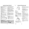
Removing the cassette deck heads (See Fig.21 and 30)
Prior to performing the following procedures, remove the top cover. Also remove the CD changer unit. Also remove the front panel assembly. 1. Remove the five screws "O" that retain the cassette deck mechanism. 2. Remove the cassette deck mechanism and place it so that the front side faces up. 3. Remove the solder from the bottom side of the head terminal and disconnect the wire. 4. Remove the screw "U" that retains the head. 5. Loosen the screw "V" that retains the head. 6. Hold the head and slide it in the direction of the arrow to remove it.
Cassette deck mechanism (Front side)
PB Head
REC/PB Head
V
U
V
U
Fig.30
Removing the 3-pin regulator (See Fig.31 and 32)
Prior to performing the following procedures, remove the top cover. Also remove the rear panel. (See Fig.33) 1. Remove the screw "W" that retains the bracket holding the 3-pin terminal regulator. 2. Remove the solder fixing the 3-pin regulator.
Power amp and supply PCB
Heat sink
W
Fig.31
Power amp and supply PCB
Heat sink
Solder on the 3-pin regulator
Fig.32
1-16
 $4.99 MX-K1 JVC
Owner's Manual Complete owner's manual in digital format. The manual will be available for download as PDF file aft…
|