|
|
|
Categories
|
|
Information
|
|
Featured Product
|
|
|
 |
|
|
There are currently no product reviews.
 ;
The service was great and the document was also great. Highly recommend!!!!
If anyone has a users manual... Please email me. need one. $ [email protected]
;
I needed a service manual as the display on my oscilloscope was very dim. I thought I'd give owner-manuals.com a try, as they advertised a huge number of manuals. Sure enough they had one listed. I bought it hoping it would be useful... actually, I bought it hoping it would be readable! I've had manuals from online sources in the past, and been very disappointed. Not this time! An excellent manual, complete, and very readable. Using it I fixed my 'scope, and as such the manual was an investment that paid off manyfold. Do I have any complaints? One very minor one - The circuit diagrams could have been scanned at a higher resolution, as some of the details were a little difficult to make out - not impossible, just not as easy as my old eyes would like! Overall, I'm very satisfied with my manual, and I will certainly be using this company again. Well done.
 ;
I Have looked for this manual for quiet a while now, I have finally found it here. I believe this is the only place they have them in a very nice scan, pages are very clear to read, some of the pages are a bit tilted but overall it is great to have this manual available for purchase. Thanks
;
This is quiet a rare manual, I Have looked for this manual for quiet a while now, I have finally found it here. I believe this is the only place they have them in a very nice scan, Excellent guide: very clear, enabling us to print readable diagram overall it is great to have this manual available for purchase. This is a complete service manual no pages are missing. Thanks
;
This SM is quiet scarce and hard to find it is an excellent Service manual, very clear to read and to print schematics and diagrams, Hi quality, Complete manual with no pages missing. I am very pleased with the manual and the fast service I have received. Great place to shop.
Good luck finding you manual...
MX-K5 Removing the heat sink & amp. board (See Fig.14 and 15)
Prior to performing the following procedure, remove the metal cover and the CD changer unit. 1. Remove the four screws I attaching the heat sink cover on the back of the body. Remove the heat sink cover. 2. Remove the four screws J attaching the heat sink & amp.board to the rear panel on the back of the body.
I
Heat sink cover
I
3. Remove the two screws K attaching the speaker terminal to the rear panel on the back of the body. 4. Disconnect the card wire from connector ACW1 & the harness from connector ACW2 on the amp. board. (See Fig.11) 5. After moving the heat sink upward, remove the claws. Then pull out the heat sink & amp.board inward.
Rear panel
Fig.14
Tuner terminal
J L
Removing the tuner board (See Fig.15 and 16)
Prior to performing the following procedure, remove the metal cover and CD changer unit. 1. Disconnect the card wire from connector CON01 on the tuner board. 2. Remove the two screws L attaching the tuner board.
Speaker terminal Heat sink
K J
Removing the rear cover
(See Fig.17)
Fig.15
Prior to performing the following procedure, remove the metal cover, CD changer unit, heat sink & amp.board and tuner pack.
Main board
1. Remove the four screws M attaching the rear panel. 2. Remove the screw M' attaching the voltage selector. (Only US/ UT/ UW)
CON01
Rear panel
M
Tuner board
Fig.16
M
M
Fig.17 1-9
 $4.99 MX-K5 JVC
Circuit Diagrams Set of circuit diagrams. The diagrams will be provided as PDF file. The file will be delivered after… 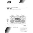 $4.99 MXK5 JVC
Owner's Manual Complete owner's manual in digital format. The manual will be available for download as PDF file aft… 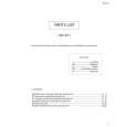 $4.99 MX-K5 JVC
Parts Catalog Parts Catalog only. It's available in PDF format. Useful, if Your equipment is broken and You need t…
|
|
|
> |
|