|
There are currently no product reviews.
 ;
Good quality, all schematics of few of models. There is also short form of user manual and regulation manual.
;
Perfect copy of the service manual. you can enlarge every page, and it comes up
with all details.
;
It´s very very nice manual with all, what i need. Original in good quality. Very fast business. Very much thanks...
;
Purchased the manual that I was looking for at a great price and could download it easily.. Great service experience and for future purchases I plan to use the site.
Thank you very much
;
Exactly what was needed to assess the product - excellent value and great service
MX-KA5
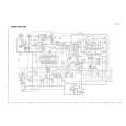
Removing the power amp and supply PCB and the power trans PCB (See Fig. 2, 29 to 31)
Prior to performing the following procedures, remove the top cover and CD changer unit. 1. Remove four screws B from the rear panel. (Fig.3) 2. Pull the heat sink cover outward. 3. Remove four screws AA from the rear panel between the heat sink holder. 4. Remove two screws X that retain the speaker terminals and AUX terminal. 5. Remove four screws YY that retains the rear panel, and then remove the rear panel. 6. Disconnect the parallel wires from the connectors FW951 on the power trans PCB. 7. Remove screws Z that retain the power amp and supply PCB and then remove the assembly. 8. Remove the clamp of AC power cord from the chassis. 9. Remove four screws that retain the power trans PCB and then remove the assembly.
Fuse (F951) 1.6A 250V X
Fuse (F952) 2.5A 250V
FW 951
AA
Clamp YY Fig.29 Fig.30
Power amp and supply PCB
Rear panel
Z
Chassis Fig.31
1-17
 $4.99 MX-KA5 JVC
Circuit Diagrams Set of circuit diagrams. The diagrams will be provided as PDF file. The file will be delivered after…  $4.99 MX-KA5 JVC
Parts Catalog Parts Catalog only. It's available in PDF format. Useful, if Your equipment is broken and You need t…
|