|
There are currently no product reviews.
 ;
Thanks for this "hard to find" service manual.
I apreciate the good quality of scanning and the pages scanned in A3 format.
;
Helpd me mont a new carradio when prewius mont was a mess.
;
Very good service and quick service, very good quality of service manual!
;
Great tape deck manual!
I'm very positively surprised, because it is a very long manual, lot of pages, drawings, diagrams, description of how to make the alignment and adjustment procedures.
It is as good as the old "Naka" manuals from the 1970's - if somebody have seen them, they know what I mean by that.
I recommend to buy this very much !
;
I am a vintage hifi collector. No way to fix that device without the appropriate service manual...thanks to your site I got it and every thing is easier now. I got the manual right after ordering: fast cheap accurate ... thank you
MX-KA6
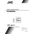
Removing the power amp and supply PCB and the power trans PCB (See Fig. 2, 29 to 31)
Prior to performing the following procedures, remove the top cover and CD changer unit. 1. Remove four screws B from the rear panel. (Fig.3) 2. Pull the heat sink cover outward. 3. Remove four screws AA from the rear panel between the heat sink holder. 4. Remove two screws X that retain the speaker terminals and AUX terminal. 5. Remove screws YY that retains the rear panel, and then remove the rear panel. 6. Disconnect the parallel wires from the connectors FW951 on the power trans PCB. 7. Remove the clamp of AC power cord from the chassis. 8. Remove four screws AB that retain the power trans PCB and then remove the assembly.
Fuse (F952) T3.15A 250V Fuse (F951) T1.6A 250V
AA
X
Fuse (F953) T1.25A 250V
Fig.29
Clamp
YY
Fig.30
Rear panel
AB Power amp and supply PCB
Chassis
Fig.31
1-17
 $4.99 MX-KA6EE JVC
Owner's Manual Complete owner's manual in digital format. The manual will be available for download as PDF file aft…
|