|
|
|
Categories
|
|
Information
|
|
Featured Product
|
|
|
 |
|
|
There are currently no product reviews.
 ;
This is a good quality scan of the Operation & Maintenance (Service) Manual for the PAL version of this high-band broadcast umatic, BVU-800P
All schematics and lineup procedures appear to be included in this one manual AFAICT.
The file size is just over 113 MB which gives an idea of the quality and number of pages.
All of the schematics, which contain some fairly small print, are easily readable when you zoom into the page.
John Thompson, Newcastle Upon Tyne, England.
;
Good quality, all schematics of few of models. There is also short form of user manual and regulation manual.
;
Perfect copy of the service manual. you can enlarge every page, and it comes up
with all details.
;
It´s very very nice manual with all, what i need. Original in good quality. Very fast business. Very much thanks...
;
Purchased the manual that I was looking for at a great price and could download it easily.. Great service experience and for future purchases I plan to use the site.
Thank you very much
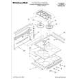
MX-KA7
Removing the cassette deck heads (See Fig. 19 and 27)
Prior to performing the following procedures, remove the top cover and both sides board. Also remove the CD changer unit. Also remove the front panel assembly. 1. Remove six screws Z that retain the cassette deck mechanism. (Fig.19) 2. Remove the cassette deck mechanism and place it so that the front side faces up. 3. Remove the solder from the bottom side of the head terminal and disconnect the wire. 4. Remove screw U that retains the head. 5. Remove screw V that retains the head. 6. Hold the head and slide it in the direction of the arrow to remove it.
PB Head
Cassette deck mechanism (Front side)
V
U
V
U
REC/PB Head
Fig.27
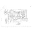
Removing the 3-pin regulator and bridge diode (See Q904, Q907, D901, D914 and Fig.28)
Prior to performing the following procedures, remove the top cover and both sides board. 1. Remove two screws A that connect the heat sink. 2. Remove two screws W that connect the heat sink. 3. Remove the solder fixing the the 3-pin terminal regulator Q904, Q907. 4. Remove the solder fixing the 4-pin bridge diode (D901, D914).
W
A
Fig.28
1-16
 $4.99 MX-KA7 JVC
Circuit Diagrams Set of circuit diagrams. The diagrams will be provided as PDF file. The file will be delivered after…  $4.99 MX-KA7 JVC
Owner's Manual Complete owner's manual in digital format. The manual will be available for download as PDF file aft…  $4.99 MX-KA7 JVC
Parts Catalog Parts Catalog only. It's available in PDF format. Useful, if Your equipment is broken and You need t…
|
|
|
> |
|