|
|
|
Categories
|
|
Information
|
|
Featured Product
|
|
|
 |
|
|
There are currently no product reviews.
 ;
Très-très bon site, facile, très bon prix.
Au futur besoin, je n’hésiterais à faire appel à vous.
Merci
;
This is the correct service manual of SHARP RX-100H(BK) DAT.
;
The ervice manual for my 1982 Kenwood KR-1000 receiver is great! Full detail on all circuits with part number detail. I will definately be ordering more manuals for my other vintage equipment! Order was fulfilled quickly! Very efficient ordering process! Thnaks for your help! Great site!
 ;
Everything in the manual was excellent except for a couple of pictures of specific areas in the unit that were a little dark. Owners Manuals re-sent the pdf file & the problem was corrected. Excellent product! George
;
Thanks for offering this item at such a good price. Proved handy in identifying the part I was looking for my set.
Thanks again.
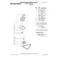
3.2.14 Removing the Power amp and supply PCB and the power trans PCB (See Fig. 3, 29 to 31) � Prior to performing the following procedures, remove the top cover and CD changer unit. (1) Remove four screws B from the rear panel. (Fig.3) (2) Pull the heat sink cover outward. Fuse(F953) (3) Remove four screws AA from the rear panel between the heat sink holder. (4) Remove four screws YY that retains the rear panel, and then remove the rear panel. (5) Disconnect the parallel wires from the connectors FW951 on the power trans PCB. (6) Remove screws Z that retain the power amp and supply PCB and then remove the assembly. (7) Remove the clamp of AC power cord from the chassis. (8) Remove four screws that retain the power trans PCB and then remove the assembly.
T1.6AL 250V
Fuse(F951) T3.15AL 250V Fuse(F952) T1.6AL 250V
Fig.29
AA
Clamp YY Fig.30 Rear panel Power amp and supply PCB
Z
Chassis Fig.31
1-18 (No.MB254)
 $4.99 MX-KB4 JVC
Circuit Diagrams Set of circuit diagrams. The diagrams will be provided as PDF file. The file will be delivered after…  $4.99 MX-KB4 JVC
Parts Catalog Parts Catalog only. It's available in PDF format. Useful, if Your equipment is broken and You need t…
|
|
|
> |
|