|
|
|
Categories
|
|
Information
|
|
Featured Product
|
|
|
 |
|
|
There are currently no product reviews.
 ;
a solid deal - quick and without any problems.
I life in europe - with downloads no loosing time
once again
 ;
got exactly what i ordered in a very timely manner. will use again for other manuals
;
I'm happy. Good quality. Very helped me with my work..............................
;
This is the second Manual I have ordered from owner-manuals, I give it five stars because it is exactly what I expected given the age of the equipment. So the contents look a bit aged and the pictures a bit grainy, it fulfills my needs and I am glad I can still get hold of them.
;
thank u so much for this manual that was so cheap that i thought it was a scam but i gambled anyway because it was too good of a deal to pass up and behold,the manual has everything and details of everything even the screws and im still amazed and very happy with my manual .so take my word and jump on it before they realize how cheap they selling thier manuals..thank you so much for taking time to read my thoughts
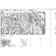
ADJUSTMENT <DECK> (FX-NH2000)
< DECK SECTION >
1. Tape Normal Speed Adjustment Settings : � Test tape : TTA�100 (Tape center) � Test point : TP1 (Rch), TP2 (Lch) � Adjustment location : SFR1 Method : Play back the test tape and adjust SFR1 so that the test point becomes 3000Hz ± 5Hz(FWD) Then check REV speed is 3000Hz ± 45Hz. 2. High Speed Check Settings : � Test tape : TTA�100 (Tape center) � Test point : TP1 (Rch), TP2 (Lch) Method : After normal speed adjustment, play back (High speed) the test tape. Then check tape speed is 6000Hz ±400Hz (FWD). 3. Head Azimuth Adjustment Settings : � Test tape : TTA�300 � Test point : TP1(Rch), TP2 (Lch) � Adjustment location : Head azimuth adjustment screw Method : Play back the 10kHz signal of the test tape and adjust screw so that the output becomes maximum.Next, perform on each FWD PLAY and REV PLAY mode. 4 PB Sensitivity Adjustment (DECK1, DECK2) Settings : � Test tape : TTA�200 � Test point : TP1 (Rch), TP2 (Lch) � Adjustment location : SFR301 (DECK1, Lch) SFR302 (DECK1, Rch) SFR303 (DECK2, Lch) SFR304 (DECK2, Rch) Method : Play back the test tape and adjust SFRs so that the output level of the test point becomes 245mV (DECK2), 260mV (DECK1). 6. REC/PB Sensitivity Adjustment (DECK2) Settings : � Test tape : TTA�602 (NORMAL) � Test point : TP1 (Rch), TP2 (Lch) � Input signal : 1kHz (LINE IN) � Adjustment location : SFR305 (Lch) SFR306 (Rch) Method : Apply a 1kHz signal and REC mode. Then adjust OSC attenuator so that the output level at the TP1, TP2 becomes 0dB (17mV). Record and play back the 1kHz signals and adjust SFRs so that the output is 0dB ± 0.5dB. 7. REC/PB Frequency Response Adjustment (DECK2) Settings : � Test tape : TTA�602 (NORMAL) � Test point : TP2 (Lch), TP1 (Rch) � Input signal : 1kHz / 10kHz (LINE IN) � Adjustment location : SFR351 (Lch) SFR352 (Rch) Method : Apply a 1kHz signal and REC mode. Then adjust OSC attenuator so that the output level at the TP1, TP2 becomes 0dB (17mV). Record and play back the 1kHz and 10kHz signals and adjust SFRs so that the output level of the 10kHz signals becomes 0dB ± 0.5dB with respect to that of the 1kHz signal. 8. REC/PB Frequency Response Check (DECK2) Settings : � Test tape : TTA�615 (CrO2) � Test point : TP2 (Lch), TP1 (Rch) � Input signal : 1kHz Method : Apply a 1kHz signal and REC mode. Then adjust OSC attenuator so that the output level at the TP1, TP2 becomes 0dB (17mV). Record and play back the 1kHz signal and check that the output is 0dB ± 2.0dB. 9. REC/PB Sensitivity Check (DECK2) Settings : � Test tape : TTA�615 (CrO2) � Test point : TP2 (Lch), TP1 (Rch) � Input signal : 1kHz (LINE OUT) Method : Apply a 1kHz signal and REC mode. Then adjust OSC attenuator so that the output level at the TP1, TP2 becomes 170mV. Record and play back the 1kHz signal and check that the output is 0dB ± 2.0dB.
5. PB Frequency Response Check (DECK1, DECK2) Settings : � Test tape : TTA�300 � Test point : TP1 (Rch), TP2 (Lch) Method : Play back the 315Hz and 10kHz signals of the test tape and check that the output ratio of the 10kHz signal with respect to that of the 315Hz signal is 0dB . Next, check that the Lch and Rch difference level of 10kHz signal is less than 2dB.
� 44 �
|
|
|
> |
|