|
|
|
Categories
|
|
Information
|
|
Featured Product
|
|
|
 |
|
|
There are currently no product reviews.
 ;
The content of the manual was not found on the Internet and was a hard find. I check the net for 5 hours until I came across this web-site. When I did find the book it Auto loaded into my IPAD PDF shelf for books for review at anytime. Overall I am satisfied with the book and it answered all my questions. This repair book is obsolete because the product I bout it for is pretty old. Thanks for the help with the download and even having the manual. Thanks 73's K5HRD
;
Excellent manual including schematics. The service was great and the manual helped complete the job.
;
It was magic after so many years to still be able to source this info. It was equally amazing to return my Pioneer receiver to it near new sound quality AFTER NEARLY 30 YEARS! Thank you for this ability!
;
Very quick and easy website to use and fast download of manual, quality of manual is excellent and will be pleased to use this service again in the future, thanks so much!
 ;
Easy and secure way to get a complete service manual of a vintage hifi component. Only some parts of the print copy are dificult to read. Nice price!
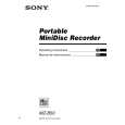
� Adjustment method of VC PWM Duty (L) (mode number: 762) 1. Select the manual mode of the test mode, and set the mode number 762. (See page 11)
R517 L
C526
digital voltmeter TP914 (VR) TP5105 (GND)
C610
LCD display
VclPWM
762
MAIN BOARD (SIDE B)
2. Connect a digital voltmeter to the TP915 (VC) on the MAIN board, and adjust [EASY SEARCH +] key (voltage up) or [EASY SEARCH --] key (voltage down) so that the voltage becomes 2.5 ± 0.02 V. Proceed to the next step without pressing X key if voltage is
C504 C503
TP915 (VC)
already adjusted.
digital voltmeter
R609 C611 R608
TP914 (VR)
C501 R505 R507 C502
5
R937 R924 R936 R923 R937 R936 R923 R924
TP5105
MAIN BOARD (SIDE B)
TP915 (VC)
629
R520
C516 C511 C508 C 09
C504 C504 C503
TP915 (VC)
C517
TP5105 (GND)
(GND)
C610
R535 R535
3. Press the X key to write the adjusted value.
Q
� Adjustment method of VREM PWM Duty (L) (mode number: 764) 1. Select the manual mode of the test mode, and set the mode number 764. (See page 11)
C514 R518 L L
R537 R537 R536
C514
C501 R505 C517 C516 C511 R520 C508 R507 C502
VrlVcl
764
TP5105 (GND)
2. Connect a digital voltmeter to the TP914 (VR) on the MAIN board, and adjust [EASY SEARCH +] key (voltage up) or
C514 R518
[EASY SEARCH --] key (voltage down) so that the voltage
3. Press the X key to write the adjusted value. � Adjustment method of VREM PWM Duty (H) (mode number: 763) 1. Select the manual mode of the test mode, and set the mode number 763. (See page 11)
LCD display
becomes 2.5 ± 0.02 V. Proceed to the next step without pressing X key if voltage is already adjusted.
digital voltmeter TP914 (VR) TP5105 (GND)
C610
VrhVcl
763
MAIN BOARD (SIDE B)
2. Connect a digital voltmeter to the TP914 (VR) on the MAIN board, and adjust [EASY SEARCH +] key (voltage up) or [EASY SEARCH --] key (voltage down) so that the voltage becomes 2.75 ± 0.02 V. Proceed to the next step without pressing X key if voltage is already adjusted.
TP915 (VC)
TP914 (VR)
C501 R505 C517 629 R520 C516 C511 C508 C 09
R536 R518 C526
R517 R517
LCD display
C526
R507 C502
3. Press the X key to write the adjusted value.
� 18 �
C503
TP5105 (GND)
 $4.99 MZB50 SONY
Owner's Manual Complete owner's manual in digital format. The manual will be available for download as PDF file aft…
|
|
|
> |
|