|
|
|
Categories
|
|
Information
|
|
Featured Product
|
|
|
 |
|
|
There are currently no product reviews.
 ;
Found this to be the manual included with the original packinging, was helpfull but did not give any detailed repair instructions.
 ;
Complete service manual, was very helpful in repairing this tapedeck.Thanks.
;
The service manual was a copy of the original from Wirlpool. The quality was good, all neccecary information was available including the service-codenumbers, so I could order the right part to be replaced for repair.
Downloding was no probem after the payment.
Thanks for the service!
;
Good,readable manual. I found other manuals that were not readable when it came to part ID, but the one downloaded from owner-manual.com was better than expected. I will do buisness with owner-manual.com again.
;
Service Manual that I received was very helpful to me. Thank you.
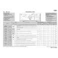
SECTION 4 TEST MODE
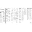
Outline � In this set, overall adjustment mode is made available by entering test mode to perform automatic adjustment of CD and MO. In the overall adjustment mode, the disc is determined whether it is CD or MO and adjustments are performed in sequence. If a fault is found, the location of the fault is displayed. Also, in servo mode, each adjustment can be automatically made. Setting the Test Mode To enter the test mode, two methods are available : 1. Entering method with key input. Turn off the HOLD switch on the set. While holding down the p key on the set, press the following remote commander keys in the following order : +n+n=n=n+n=n+n =nPnP 2. Entering method by shorting the test point Solder bridge the test point TAP801 (TEST) on the main board (connect IC801 pin #� to GND), and turn on the POWER.
C805
Configuration of Test Mode The test mode has the configuration given below.
VOL + key p key Overall adjustment mode (Auto?) p key p key VOL � key p key Adjustment � key mode (Manu ?) Servo mode 000 +, � keys Audio mode 100 +, � keys Servo mode 300 Displays of the LCD on the remote commander are shown in parentheses.
+, � keys
� key
(Start ?)
RB801
TP911
R811 R810
C807 C806
TAP801
Test mode Short : Test mode Open : Normal mode
to move the optical pick-up to the outer circumference and to the inner circumference respectively. � When entering another mode, refer to the configuration of test mode. 1. Structure of Servo Mode
Servo mode 000 p key � key
+, � keys
IC801
is set
TP819
R808
TP808
Servo Mode � Set the test mode, press the VOL � key and use the � key to set the servo mode. � When the servo mode is set, use the + key and the = key
Display when test mode
Offset adjustment 010
� key
p key
011 to 013 *1 � key
Releasing the Test Mode 1. When test mode was entered with key input, turn off the POWER. 2. When test mode was entered by shorting the test point, turn off the POWER and open the solder bridge of TAP801 (TEST MODE) on the main board. Operation of Setting on Test Mode When the test mode is set, the LCD displays the following :
1
p key
Laser power adjustment 020
� key
021 to 024 p key *1 � key 2 (See page 8) 3
V1. 000
ROM version display LCD on remote commander
� The cycle - the above ROM version display n All lit n All off - is repeated. (The ROM version is constantly displayed.) � When the PLAY MODE key is pressed and hold down, the display at that time is held so that display can be checked.
*1 Repeatedly press � key to change the mode. (Refer to the following list for a description of each mode.)
�7�
 $4.99 MZE33 SONY
Owner's Manual Complete owner's manual in digital format. The manual will be available for download as PDF file aft…
|
|
|
> |
|