|
|
|
Categories
|
|
Information
|
|
Featured Product
|
|
|
 |
|
|
There are currently no product reviews.
 ;
We received the manual in a timely manner and it was exactly what we were expecting. Excellent replacement for original Service Manual.
All schematics are very legible. We are really satisfied.
;
We received the manual in a timely manner and it was exactly what we were expecting. Excellent replacement for original Service Manual.
All schematics are very legible. We are really satisfied.
;
We received the manual in a timely manner and it was exactly what we were expecting. Excellent replacement for original Service Manual.
All schematics are very legible. We are really satisfied.
;
We received the manual in a timely manner and it was exactly what we were expecting. Excellent replacement for original Service Manual.
All schematics are very legible. We are really satisfied.
;
We received the manual in a timely manner and it was exactly what we were expecting. Excellent replacement for original Service Manual.
All schematics are very legible. We are really satisfied.
5-4-4. Vc PWM Duty (H) adjustment method 1. Set the Manual mode and set the item No. to 765. (See page 12) LCD display
5-5. OVERALL ADJUSTMENT MODE
5-5-1. Overall adjustment mode structure
TEST MODE (Display Check Mode)
765 VchPWM
2. Connect a digital voltmeter to TP901 on the main board and adjust + key and � key on the remote control so that the voltage is at 2.75V ± 15 mV.
. key
Overall CD Adjustment
x
key
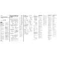
Digital voltmeter Main board TP901 (VC) TP912 (GND)
. key > N key
> N key
3. Press X key to write the adjustment value. Note : Do not Press the X key if the adjustment value is already set. 5-4-5. Vrem PWM Duty (H) adjustment method 1. Set the Manual mode and set the item No. to 766. (See page 12) LCD display
Overall MO Adjustment
x
key
Note: The overall adjustments should be always performed in the sequence of CD t MD adjustments. 5-5-2. Overall CD and MO adjustment method 1. Set the TEST MODE (see page 11) and press � key to set the Overall Adjustment mode. LCD display
766 VrhVch
2. Connect a digital voltmeter to TP903 on the main board and adjust + key and � key on the remote control so that the voltage is at 2.6 ± 15 mV.
Digital voltmeter Main board TP903 (VR) TP912 (GND)
000 AssyFF
2. Insert CD disc in the set, and press . key to set the Overall CD Adjustment mode. Automatic adjustments are made. LCD display
XXX CD RUN
XXX: Item No. for which an adjustment is being executed. 3. If NG in the overall CD adjustments, return to Reset NV and perform the adjustment again. LCD display
TP903
3. Press X key to write the adjustment value. Note : Do not Press the X key if the adjustment value is already set.
MAIN BOARD (SIDE B )
XXX NG
XXX: NG item No. 4. If OK through the overall CD adjustments, then perform overall MO adjustments. LCD display
IC501
IC901
XXX CD OK
IC552 TP912
5. Insert MO disc in the set, and press > N key to set the Overall MO Adjustment mode. Automatic adjustments are made. LCD display
CN501
TP901
XXX MO RUN
XXX: Item No. for which an adjustment is being executed.
� 16 �
 $4.99 MZE90 SONY
Owner's Manual Complete owner's manual in digital format. The manual will be available for download as PDF file aft…
|
|
|
> |
|