|
|
|
Categories
|
|
Information
|
|
Featured Product
|
|
|
 |
|
|
There are currently no product reviews.
 ;
Excellent manual, detailed, very useful! Exactly what I needed, I'd recommend it to all who need it. Although images are scanned easily readable and explicit. A valuable tool product at a price more than modest, take it with confidence and you will not regret it!
;
Clear and complete service manual. Easy now to restore my old Kenwood KD-1500.
Thanks a lot.
;
Thanks for this "hard to find" service manual. This Sony PS212A is a very good turntable that needed to be restored !
 ;
Excellent quality on these manuals. Same as having the original printed manual and incredibly useful when doing a custom install like me. Keep it up on the good work.
;
This is an excellent information source. Great quality and tons of info regarding technical service for the Technics SH8065.
MZ-E909 SECTION 4 TEST MODE
4-1. GENERAL
� When entered in the TEST MODE, this set provides the Overall Adjustment mode which allows CD and MO discs to be automatically adjusted. In the Overall Adjustment mode, the system discriminates between CD and MO discs, performs adjustments in sequence automatically, and displays the faulty location if any fault is found. In the Manual mode, selected adjustments can be performed automatically. � The attached remote control is used to operate the TEST MODE. Unless otherwise specified in the text, the key means that on the remote control.
C613 C605
Remote control LCD
888
F 1SHUFF PGM u
SOUND 1 2 BASS 1 2
All on
All off
008 V1.000
Microprocessor version display
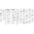
4-2. SETTING THE TEST MODE
4-2-1. How to set the TEST MODE To set the TEST MODE, two methods are available. 1 Solder bridge and short TAP601 (TEST) on the main board. Then turn on the power.
C810 C699
C606
� Press and hold down X to hold the current display while the key is being pressed.
MAIN BOARD (SIDE A)
TAP601 SHORT: TEST MODE OPEN: NORMAL MODE
TP921
R607
R601 R80
C802
4-2-3. How to release the TEST MODE When method 1 was used: Turn off the power and open the solder bridge on TAP601 on the main board. Note: The solder should be removed clean. The remaining solder may make a short with the chassis and other part. When method 2 was used: Turn off the power. Note: If electrical adjustment (see page 11) has not been finished completely, always start in the test mode. (The set cannot start in normal mode)
C610
4-3. TEST MODE STRUCTURE
Test Mode (Display Check Mode)
2 In the normal mode, operate the keys on the set and those on the remote control as specified below: Turn on HOLD switch on the set. Holding down x (STOP) key on the set, press the keys on the remote control in the following sequence: >N t >N t . t . t >N t . t >N t . t X t X 4-2-2. Operations when the TEST MODE is set When the TEST MODE is entered, the system switches to the display check mode within the TEST MODE. From this mode, the other Test modes can be accessed. When the TEST MODE is set, the LCD repeats a cycle of the following displays:
.
+ key Manual Mode
x
key + key Servo Mode Audio Mode
Power Mode key OP Alignment Mode or key Overall Adjustment Mode
x
key
DISPLAY key
x
key key
Self-diagnostic Display Mode
>B x
key Sound Skip Check Result Display Mode
DISPLAY key (Press and hold down about 3 sec) Key Check Mode Terminate key checking or open the top panel.
8
 $4.99 MZE909 SONY
Owner's Manual Complete owner's manual in digital format. The manual will be available for download as PDF file aft…
|
|
|
> |
|