Thr Video Recorder i have is quiet Old and the Producer could Not help me. So i w as very glad to find an offer for the owners Manual for a very fair Price.a I obtained the original Manual very quick and I am happy to have it now.
Text excerpt from page 13 (click to view)
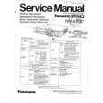
GAS EQUIPMENT ASSEMBLY
SOLENOID VALVE THERMOCOUPLE BURNER MOUNTING SCREWS
FIG. 12 BURNER TUBE .
INLET FITTING BURNER JET SPARK ELECTRODE MANUAL SHUTOFF VALVE Shown in open position PRESSURE TEST PORT
E.
1. 2. 3. 4. 5. 6. 7.
8. 9.
The correct operating pressure is 11 inches of water column. The correct place to take the LP gas pressure is at the test port just ahead of the burner jet. (See FIG. 12). Inspect the flue baffle. It should be reasonably clean and free of soot. Heavy soot formation indicates improper functioning of the burner. The flue and burner both require cleaning in the following manner: Unplug the refrigerator power cord from the 120 volt AC outlet. (See FIG. 3). Disconnect or shut off the 12 volt power to the refrigerator. Turn manual shutoff valve to OFF. (See FIG. 1). Remove cover from the burner housing. (See FIG. 1). Disconnect the wire from the high voltage electrode. Remove the burner mounting screws and remove the burner assembly. (See FIG. 12). Remove the wire and the flue baffle from the top of flue tube. Clean the flue from the top using a flue brush. Blowing compressed air into the flue will not properly clean soot and scale out of the flue tube. Replace the flue baffle. Clean burner tube with a brush. Blow out burner with compressed air. Before removing burner jet, clean burner area of soot and scale that fell out of flue tube. Remove the burner jet. Soak the jet in wood alcohol and blow it out with compressed air. Reinstall and tighten burner jet. NOTE: The color of the flame shall be clear blue over the slots of the burner. (See FIG. 13). Clear blue color of flame
! WARNING
DO NOT use a wire or pin when cleaning the burner This can cause damage to the refrigerator or create a fire hazard. jet as damage can occur to the precision opening.
10. Reinstall burner, being careful that the end of the burner fits into the slot on the burner bracket. Check to make sure slots are centered under the flue tube 11. Be sure to reconnect the wire to high voltage elecand the thermocouple is positioned properly (tip of thermocouple extends over two slots of burner). trode. Check the electrode for proper location and gap. (See FIG. 14). Electrode
FIG. 14
1/8� to 3/16� (3-5 mm) Burner tube 12. Turn on manual gas shutoff valve and check all fittings for leaks. 13. Connect 120 volt power cord to the outlet and reconnect or turn on the 12 volt DC power. 14. Check LP gas safety shutoff. See page 6.