|
There are currently no product reviews.
 ;
Very nice and real Service Manual, I didn't thought it actually exist in the real world at all.
 ;
VERY NICE FOR COURTESY AND PRECISION!.
tHE SITE IS VERY IMPORTANT FOR ALL DEVICES
vERY GOOD
;
+++ Is is fine, that was what i looking for. Thanks! +++
;
A very good complete archive, i am very satisfied for document.
;
The Service Manual received was helpful. The electronic information is exactly what I needed.
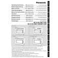
4. Remove the 4 screws holding magnetron. 5. Remove 2 screws holding thermal cutout. 6. Remove the mounting bracket from magnetron and install it on the new magnetron.
Lower magnetron
1. Discharge electric charge remaining on the high voltage capacitors. 2. Remove the entire rear panel by removing screws as shown. 3. Carefully place the unit on its left side (H.V.Capacitor side). 4. Remove the cover by removing 2 screws. 5. Remove the 4 screws holding magnetron by inserting screwdriver through the 4 openings on bottom plate. 6. Remove 2 screws holding thermal cutout. 7. Remove the mounting bracket from magnetron and install it on the new magnetron.
NOTE: To prevent microwave leakage, tighten mounting screws properly making sure there is no gap between the waveguide and the magnetron.
CAUTION When connecting 2 filament lead wires to the magnetron terminals, be sure to connect the lead wires in the correct position. The lead wire with blue connector should be connected to �FA terminal� and white or pink one should be connected to �F terminal�.
16
|