|
|
|
Categories
|
|
Information
|
|
Featured Product
|
|
|
 |
|
|
There are currently no product reviews.
 ;
Very good reproduction (copy) of original manual. Didn't have a parts list, but schematic was completely labeled with parts. Complete instructions on how to adjust mechanical functions of the 8-track deck. Well worth having and at a very reasonable cost.
;
It's a full manual. All the parts are in there. I haven't found the problem yett, but I am working on it; hope I can rebuild the part myself. To make it more secure and unbreakable this time. Because the part has failed several times before and costs a lot to let it be repaired.
Thanks so much for this rich illustrated and parted manual.
;
I downloaded the document. The manual was complete, well scanned and everything was legible. I could zoom in see what I needed to know. There's not much more that you can ask.
;
It was complete service manual with all needed service informations. Thanks.
 ;
El manual esta muy detallado, los numeros de partes y los esquemas de despiece son correctísimos y muy claros, tanto para los técnicos experimentados como para los novatos.
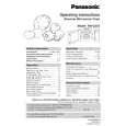
NN-G354MF / NN-G354MM
4 MEASUREMENTS AND ADJUSTMENTS
4.1. Adjustment of primary latch switch, secondary latch switch and short switch. 4.2. Measurement of microwave output
The output power of the magnetron can be determined by performing IEC standard test procedures. However, due to the complexity of IEC test procedures, it is recommended to test the magnetron using the simple method outlined below. Necessary Equipment: � 1 liter beaker � Glass thermometer � Wrist watch or stopwatch NOTE: Check the line voltage under load.Low voltage will lower the magnetron output. Take the temperature readings and heating time as accurately as possible. 1. Fill the beaker with exactly one liter of tap water. Stir the water using the thermometer and record the water�s temperature. (recorded as T1). 2. Place the beaker on the center of glass tray. Set the oven for High power and heat it for exactly one minute. 3. Stir the water again and read the temperature of the water. (recorded as T2). 4. The normal temperature rise at High power level for each model is as shown in table.
TABLE (1L-1min.test) RATED OUTPUT TEMPERATURE RISE 800W(IEC705-88) Min. 14.4°F (8°C)
1. Mount the Primary latch swith, the Secondary latch switch and the Short switch to the door hook assembly as shown in table. NOTE: No specific individual adjustments during installation of Primary latch switch,Secondary latch switch or Short switch to the door hook is necessary. 2. When mounting the door hook assembly to the oven assembly, adjust the door hook assembly by moving it in the direction of the arrows in the illustration so that the oven door will not have any play in it. Check for play in the door by pulling the door assembly. Make sure that the latch keys move smoothly after adjustment is completed. Completely tighten the screws holding the door hook assembly to the oven assembly. 3. Reconnect the short switch and check the coninuity of the monitor circuit and all latch switches again by following the component test procedures.
7
|
|
|
> |
|