|
|
|
Categories
|
|
Information
|
|
Featured Product
|
|
|
 |
|
|
There are currently no product reviews.
 ;
Dear Sirs,
Thank you for the fast support, the manual does provide all necessary information to repair the radio. All schematics are in a good quality for reading.
The manual fits 100% to my requirements as a technican.
Kind regards Thomas
;
the big video recorder format s-vhs many features delicate in loading system of the cassette. Such machines are no longer manufactured, it would be too expensive.
 ;
THIS MANUAL IS VERY GOOD AND VERY CLEAR
PLEASE NOTE IT DOES NOT CONTAIN THE SETUP INFORMATION TO ALIGHN THE GEARS IN THE CD MECH IT DOES SHOW ALL THE PARTS AND THEIR LOCATIONS .
;
Complete service and operation manual. All schematics are there, all circuit boards AND add-on boards. Including exploded views ,component names and specifications. Also electrical and mechanical adjustment procedures are in this manual. This manual also covers the more advanced BR-S811E unit. Scan quality is fair and usable.
;
High quality scan of original Service Manual. Everything´s fine!
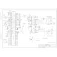
DESCRIPTION OF OPERATING SEQUENCE
1. Variable power cooking control
The coil of power relay B (RY1) is energized intermittently by the digital programmer circuit, when the oven is set at any power selection except for High power position. The digital programmer circuit controls the ON-OFF time of power relay B contacts in order to vary the output power of the microwave oven from �Low� to �High� power. One complete ON and OFF cycle of power relay B is 22 seconds. The relation between indications on the control panel and the output of the microwave oven is as shown in table. NOTE: The ON/OFF time ratio does not correspond with the percentage of microwave power since approximately 2 seconds are required for heating of magnetron filament. P10 P9 P8 MEDIUM-HIGH P7 MEDIUM P6 P5 P4 MEDIUM-LOW P3 P2 P1 DEFROST P3 HIGH
Variable Power Cooking
POWER SETTING OUTPUT POWER(%) APPROX. ON (SEC) 100% 90% 80% 70% 60% 50% 40% 30% 20% 10% 30% 22 22 22 22 22 22 22 22 15 8 22 OFF (SEC) 0 0 0 0 0 0 0 0 7 14 0 ON-OFF TIME OF POWER RELAY B (RY1)
2. Inverter Power Supply Circuit NEW H,V
This Inverter Power Supply Circuit supplies 4,000V DC to the magnetron tube from the line voltage,120v 60Hz AC input. functions as the H.V. transformer, the H.V.capacitor and H.V.Diode. 1. The AC input voLtage 120V 60HZ is rectified to DC voltage immediately. 2. DC voltage will be supplied to the switching devices called IGBT. These devices will be switched ON-OFF by the 20 to 40 kHz PWM. (pulse width modulation) signal from the microcomputer in the DPC. 3. This drives the High voltage transformer to increase up to 2,000V AC and approximately 3V AC by means of transformer. 4. Then the half-wave doubler voltage rectifier circuit, consisting of the HV diodes and Capacitors, generates the necessary 4,000V DC needed for the magnetron. 5. Output power of the magnetron tube is always monitored by the signal output from the current transformer built into the inverter ciruit. 6. Then this signal will be fed back to the microcomputer in the DPC to determine operating conditions and output necessary to control PWM signal to the inverter Power Supply to control output power.
Inverter Turbo Defrost
SELECTED WEIGHT 1.0LB 6.0LB COOKING TIME 4 min.28 sec.
25 min.00 sec.
3. Inverter Turbo Defrost
When this Auto Control feature is selected and the Start Pad is tapped: (A) The digital programer circuit determines the power level and cooking time to complete cooking and indicates the operating state in the display window. Table shows the corresponding cooking times for respective serving by categories. (B) When cooking time the display window has elapsed, the oven tums off automatically by a control signal from the digital programmer circuit.
-9-
|
|
|
> |
|