|
There are currently no product reviews.
 ;
As Always these people were very rapid and efficient. A great job helping hobbiest and workers!!! Thank you a lot!
;
Excellent printing quality.
A complete and very usefull service manual with all details.
GREAT SERVICE AT VERY LOW PRICE!
A+++++++++++++++++++++++++
;
Excellent printing quality.
A complete and very usefull service manual with all details.
GREAT SERVICE AT VERY LOW PRICE!
A+++++++++++++++++++++++++
;
Thank you for providing quickly a manual so old! very good job clear and understandable!
;
Excellent printing quality.
A complete and very usefull service manual with all details.
GREAT SERVICE AT VERY LOW PRICE!
A+++++++++++++++++++++++++
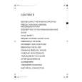
IV.
EXPOSURE
SYSTEM
2. Removing
the Thermal
Fuse
A. SCANNER 1. Removing the Scanning Lamp
1) Unplug the copier. 2) Remove the control panel and copyboard glass. 3) Unscrew the two screws and remove the reflector.
1) Remove the control panel and copy. board glass. 2) Grasp the rear of mirror 1 mount move it to the right, and bring it to the part shown in Figure 4-44. Note: Be sure to hold the rear of the mirror mount at the rear when moving it. 3) Unscrew the two mounting screws, then remove the thermal fuse. 1
0 Screws
@ Reflector Figure 4-42 @ Mounting screws @ Mirror @ Thermal fuse Fiugre 4-44 1 mount
4) Push the contact (rear) in the direction of the arrow and remove the scanning lamp.
@ Lamp contact
0
Scanning lamp
Figure 4-43 Note: 1. The scanning lamp will be hot, if it has been operating recently. 2. Never touch the surface of the scanning lamp, with bare hands. 3. If the scanning lamp is dirty, wipe it with a dry cloth. If there are any fingerprints or skin oil on it, clean them off with solvent.
4-14
COPvllI6HT
0
1986 CAllow MC.
CA101
IP-1215
RN.0
WA.
1988
PRIYTEO
II JAPAN IIMPAIME
AU JAPOW]
 $4.99 NP1215S CANON
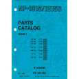
Parts Catalog Parts Catalog only. It's available in PDF format. Useful, if Your equipment is broken and You need t…
|