|
|
|
Categories
|
|
Information
|
|
Featured Product
|
|
|
 |
|
|
There are currently no product reviews.
 ;
I want to give you a real heads-up for your desire to enable such people as I to acquire the information I need to maintain the older types of equipment such as this Akai HXA351W. You do a swell job with all the processes you have to perform so I can have a legible, thus usable
document which does not send me crazy trying to figure out the blurry text of a bad copy.
Very well done, Thomas.
;
This manual is very well presented and after printing out looks about as close to an original as I think you can get. The quality is second to none.
The content of the manual is comprehensive and I think it would be well suited to an audio repair professional which I'm not but I did find it very informative and helpful.
The cost of the manual is more than covered by the money I'll save when I change the keep memory battery now I have the relavant info.
Very pleased with my purchase and can recommend it wholeheartedly as I can other manuals I've downloaded from this site.
Regards
Limey Alex
 ;
Complete manual including mechanical part in good pdf quality. Shaded greys of the pcb due to pdf not perfect but usable.
;
Nice pdf file of the manual sent promptly. Thanks.
;
Complete MFG Service Manual at a good price FAST !
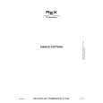
PRACTICAL SERVICE FIGURE
u
FRONT C.B
<TUNER
SECTION>
<DECK
SECTION> 3000Hz * 45Hz Less than 0,35% (W.R.M,S) 30- 60g-cm (FWD, REV) 2- 5g-cm (FWD, REV) 280mV* 3dB (SP OUT 2V) -1,8V * 3.OdB (NORM) Less than 2,0% (NORM, CrOJ Less than 30mV(NORM) Less than 30mV(NORM) More than 60dB (at 125Hz, +1OVU)
-1
SFR201
o+
9
<FM SECTION> IHF Sensitivity: Less than 10/9/9dB (THD 3%) [at 87,5 /98.0 / 108.OMHZ] S/N 50dB Quieting sensitivity : bXS than 35dB [at 98.OMHZ] Signal to noise ratio : Mono : More than 68dB Stereo: More than 66dB [at 98.OMHZ] Distortion : Mono: Less than 1.2% Stereo: Less than 2.0% [at 98.OMHZ] Auto stop Ievel : 25dB * 10dB [at 98.OMHZJ Stereo separation : More than 25dB [at 98.OMHZ] Intermediate frequency : 10.7MHz <MW SECTION> Sensitivity : (S/N 20 dB) Signal to noise ratio :
Tape speed : Wow & flutter: Take-up torque: Back tension : PB output level : REC/PB output level : Distortion (REC/PB) : Noise level (PB) : Noise level (REC/PB) : Erasing ratio:
r
I
m
1
Less than 54/ 52/ 52dB [at 603 /1000 /1404kHzJ Mono : More than 36dB [at 1000kHzJ
PATTERN SIDE
DECK-1 P. HEAD DECK-1 R / P / E HEAD
Stereo: More than 34dB [at 1000kHz] Mono: Less than 1.5% [at 1000kHz] Stereo: Less than 4,0% [at 1000kHz] Auto stop level : 52dB +10/-l5dB [at 1000kHz] Stereo separation: More than 15dB [at 1000kHz] Intermediate frequency : 450kHz Distortion :
o
FWD
10
< DECK
SECTION> 12. PB Sensitivity Check (DECK 1, DECK 2) Settings: Test tape: l�T�A-200 Test point: TP8(Lch), TP9(Rch) Method: Play back the test tape so that the output level at TP8(Lch), TP9(Rch) becomes 110mV* 3,0dB.
q q
9. Tape Speed Adjustment Settings: � Test tape: TTA-100 Test point: TP8(Lch), TP9(Rch) Adjustment location: SFR201 Method: Play back the test tape and adjust SFR201 so that the frequency counter reads 3000Hz * 5Hz,
q q
10. Head Azimuth Adjustment (DECK 1, DECK 2) Settings: Test tape: TI�A-300 �* Test point: TP8(Lch), TP9(Rch) Adjustment location: Head azimuth adjustment screw Method: Play back (FWD) the 10kHz signal of the test tape and adjust screw so that the output becomes maximum. Next, perform on REV PLAY mode.
q q
13. REC/PB Frequency Response Check Settings: Test tape: �ITA-615 (Normal) � Test point: TP8(Lch), TP9(Rch) Input signal : 1kHz / 8kHz (LINE IN) Method : Apply a lkHz signal and REC mode. Then adjust OSC attenuator so that the output level at the TP8(Lch), TP9(Rch) becomes 8-10mV. Record and play back the lkHz and 10kHz signals and check that the output is OdB a 4,0dB.
q q
11. PB Frequency Response Check (DECK 1, DECK 2) Settings: Test tape: lTA-330 Test point :TP8(Lch), TP9(Rch) Method: Play back the 315Hz and 8kHz signals of the test tape and check that the output ratio of the 8kHz signal with respect to that of the 3 15Hz signal is within *5dB.
q q
14. REC/PB Sensitivity Check Settings: � Test tape: �ITA-615 (Normal) Test point : TP8(Lch), TP9(Rch) Input signal : 1kHz (LINE IN) Method: Apply a 1kHz signal and REC mode, Then adjust OSC attenuator so that the output level at the TP8(Lch), TP9(Rch) becomes 80- 100mV, Record and play back the 1kHz signals and check that the output is -0.2 t 3,5dB,
q q
-27-
-28-
 $4.99 NSXA202 AIWA
Owner's Manual Complete owner's manual in digital format. The manual will be available for download as PDF file aft…
|
|
|
> |
|