|
|
|
Categories
|
|
Information
|
|
Featured Product
|
|
|
 |
|
|
There are currently no product reviews.
 ;
Excellent scan quality. A complete and very useful manual with all details.
Great service at low price A+++++++++++++++++
;
The manual is very good quality. very good graphics. complete
;
Excellent printing quality.
A complete and very usefull service manual with all details.
GREAT SERVICE AT VERY LOW PRICE!
A+++++++++++++++++++++++++
;
Excellent, very professional, fast, reliable, congratulations thank you.
;
Excellent printing quality.
A complete and very usefull service manual with all details.
GREAT SERVICE AT VERY LOW PRICE!
A+++++++++++++++++++++++++
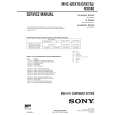
B FRONT C.B
14
D981
FL901
TP11 IC901 L951 + C913 GND
1
3 0
TP11 (KEY-SCAN) (GND)
< CR NETWORK FILTER > 10µF 10µF 1k� 1SS133 1k� 0.1µF 47k� TO FREQUENCY COUNTER
E DECK C.B
SFR1 9
DECK�1 P HEAD DECK�2 R/P/E HEAD
FWD REV
9
8
< DECK SECTION >
8. Tape Speed Adjustment (DECK 2) Settings : � Test tape : TTA�100 � Test point : TP8(Lch), TP9(Rch) � Adjustment location : SFR1 Method : Play back the test tape and adjust SFR1 so that the frequency counter reads 3000Hz ± 5Hz (FWD) and FWD SPEED ± 45Hz (REV). 9. Head Azimuth Adjustment (DECK 1, DECK 2) Settings : � Test tape : TTA�330 � Test point : TP8(Lch), TP9(Rch) � Adjustment location : Azimuth adjustment screw Method : Play back (FWD) the 8kHz signal of the test tape and adjust screw so that the output becomes maximum. Next, perform on REV PLAY mode. 10. PB Frequency Response Check (DECK 1, DECK 2) Settings : � Test tape : TTA�330 � Test point :TP8(Lch), TP9(Rch) Method : Play back the 315Hz and 8kHz signals of the test tape and check that the output ratio of the 8kHz signal with respect to that of the 315Hz signal is within 5dB. 11. PB Sensitivity Check (DECK 1, DECK 2) Settings : � Test tape : TTA�200 � Test point : TP8(Lch), TP9(Rch) Method : Play back the test tape and check that the output level of the test point is 110mV ± 3dB.
12. REC/PB Frequency Response Adjustment (DECK 2) Settings : � Test tape : TTA�602 � Test point : TP8(Lch), TP9(Rch) � Input signal : 1kHz / 8kHz (LINE IN) � Adjustment location : SFR351 (Lch), SFR352 (Rch) Method : Apply a 1kHz signal and REC mode. Then adjust OSC attenuator so that the output level at the TP8, TP9 becomes -20VU (-26dBV). Record and play back the 1kHz and 8kHz signals and adjust SFRs so that the output of the 8kHz signals becomes 0dB ± 0.5dB with respect to that of the 1kHz signal. 13. REC/PB Sensitivity Check (DECK 2) Settings : � Test tape : TTA�602 � Test point : TP8(Lch), TP9(Rch) � Input signal : 1kHz (LINE IN) Method : Apply a 1kHz signal and REC mode. Then adjust OSC attenuator so that the output level at TP8, TP9 becomes 0VU (-6dBV). Record and play back the 1kHz signals and check that the output is -2dB ± 3.5dB.
< FRONT SECTION >
14. µ-con OSC Adjustment Settings : � Test point : TP11,(KEY-SCAN), GND � Adjustment location : L951 Method : Connect a frequency counter across TP11 and GND via a CR network filter. Then adjust L951 so that the test point becomes 184.94Hz ± 0.18Hz.
� 32 �
|
|
|
> |
|