|
|
|
Categories
|
|
Information
|
|
Featured Product
|
|
|
 |
|
|
There are currently no product reviews.
 ;
got exactly what i ordered in a very timely manner. will use again for other manuals
 ;
I'm happy. Good quality. Very helped me with my work..............................
;
This is the second Manual I have ordered from owner-manuals, I give it five stars because it is exactly what I expected given the age of the equipment. So the contents look a bit aged and the pictures a bit grainy, it fulfills my needs and I am glad I can still get hold of them.
;
thank u so much for this manual that was so cheap that i thought it was a scam but i gambled anyway because it was too good of a deal to pass up and behold,the manual has everything and details of everything even the screws and im still amazed and very happy with my manual .so take my word and jump on it before they realize how cheap they selling thier manuals..thank you so much for taking time to read my thoughts
;
I do not have very much to say.
The price is quite covenient, delivery was better as promised (about 12 ours, against the specified 24 hours if I remember well), and the quality of the PDF is more than acceptable.
The Service Manual of Sansui R30 itself is also satisfactory: good graphic for schematics and layouts, simple and well structured.
Giovanni Bianchi
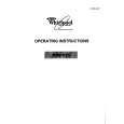
B FRONT C.B
14
D981
FL901
TP11 IC901 L951 + C913 GND
1
3 0
TP11 (KEY-SCAN) (GND)
< CR NETWORK FILTER > 10µF 10µF 1k� 1SS133 1k� 0.1µF 47k� TO FREQUENCY COUNTER
E DECK C.B
SFR1 9
DECK�1 P HEAD DECK�2 R/P/E HEAD
FWD REV
9
8
< DECK SECTION >
8. Tape Speed Adjustment (DECK 2) Settings : � Test tape : TTA�100 � Test point : TP8(Lch), TP9(Rch) � Adjustment location : SFR1 Method : Play back the test tape and adjust SFR1 so that the frequency counter reads 3000Hz ± 5Hz (FWD) and FWD SPEED ± 45Hz (REV). 9. Head Azimuth Adjustment (DECK 1, DECK 2) Settings : � Test tape : TTA�330 � Test point : TP8(Lch), TP9(Rch) � Adjustment location : Azimuth adjustment screw Method : Play back (FWD) the 8kHz signal of the test tape and adjust screw so that the output becomes maximum. Next, perform on REV PLAY mode. 10. PB Frequency Response Check (DECK 1, DECK 2) Settings : � Test tape : TTA�330 � Test point :TP8(Lch), TP9(Rch) Method : Play back the 315Hz and 8kHz signals of the test tape and check that the output ratio of the 8kHz signal with respect to that of the 315Hz signal is within 5dB. 11. PB Sensitivity Check (DECK 1, DECK 2) Settings : � Test tape : TTA�200 � Test point : TP8(Lch), TP9(Rch) Method : Play back the test tape and check that the output level of the test point is 110mV ± 3dB.
12. REC/PB Frequency Response Adjustment (DECK 2) Settings : � Test tape : TTA�602 � Test point : TP8(Lch), TP9(Rch) � Input signal : 1kHz / 8kHz (LINE IN) � Adjustment location : SFR351 (Lch), SFR352 (Rch) Method : Apply a 1kHz signal and REC mode. Then adjust OSC attenuator so that the output level at the TP8, TP9 becomes -20VU (-26dBV). Record and play back the 1kHz and 8kHz signals and adjust SFRs so that the output of the 8kHz signals becomes 0dB ± 0.5dB with respect to that of the 1kHz signal. 13. REC/PB Sensitivity Check (DECK 2) Settings : � Test tape : TTA�602 � Test point : TP8(Lch), TP9(Rch) � Input signal : 1kHz (LINE IN) Method : Apply a 1kHz signal and REC mode. Then adjust OSC attenuator so that the output level at TP8, TP9 becomes 0VU (-6dBV). Record and play back the 1kHz signals and check that the output is -2dB ± 3.5dB.
< FRONT SECTION >
14. µ-con OSC Adjustment Settings : � Test point : TP11,(KEY-SCAN), GND � Adjustment location : L951 Method : Connect a frequency counter across TP11 and GND via a CR network filter. Then adjust L951 so that the test point becomes 184.94Hz ± 0.18Hz.
� 32 �
|
|
|
> |
|