|
|
|
Categories
|
|
Information
|
|
Featured Product
|
|
|
 |
|
- SPECIFICATIONS (NSX - MT70 U AND NSX - MT75 U)
- SPECIFICATIONS (NSX - AV85 LH, HE)
- SPECIFICATIONS (NSX - AV85 EZ)
- PROTECTION OF EYES FROM LASER BEAM DURING SERVICING
- PRECAUTION TO REPLACE OPTICAL BLOCK
- ELECTRICAL MAIN PARTS LIST
- TRANSISTOR ILLUSTRATION
- FL GRID ASSIGNMENT & ANODE CONNECTION
- BLOCK DIAGRAM - 1 (PROLOGIC)
- BLOCK DIAGRAM - 2 (MAIN/FRONT)
- WIRING - 1 (MAIN : EZ)
- SCHEMATIC DIAGRAM - 1 (MAIN : EZ)
- SCHEMATIC DIAGRAM - 2 (MAIN : LH, U)
- WIRING - 2 (MAIN : LH,U)
- WIRING - 3 (MAIN : HE)
- SCHEMATIC DIAGRAM - 3 (MAIN : HE)
- SCHEMATIC DIAGRAM - 4 (FRONT)
- WIRING - 4 (FRONT)
- WIRING - 5 (PROLOGIC : U, LH, HE)
- SCHEMATIC DIAGRAM - 5 (PROLOGIC : U, LH, HE)
- WIRING - 6 (PROLOGIC : EZ)
- SCHEMATIC DIAGRAM - 6 (PROLOGIC : EZ)
- WIRING - 7 (PT)
- WIRING - 8 (DECK)
- SCHEMATIC DIAGRAM - 7 (TUNER FRONTEND/FAN)
- IC BLOCK DIAGRAM
- IC DESCRIPTION
- ADJUSTMENT - 1 < TUNER/DECK >
- PRACTICAL SERVICE FIGURE
- TAPE MECHANISM EXPLODED VIEW 1/1
- TAPE MECHANISM PARTS LIST 1/1
- MECHANICAL EXPLODED VIEW 1/1
- MECHANICAL PARTS LIST 1/1
- SPRING APPLICATION POSITION
- SPEAKER DISASSEMBLY INSTRUCTIONS
- SPEAKER PARTS LIST
- ACCESSORIES/PACKAGE LIST
- REFERENCE NAME LIST
There are currently no product reviews.
 ;
Very fast and perfect delivery. Clear and well scanned. A lot of work professionally realized.
Again thak you a lot
 ;
This manual is accurate and of high quality. It is only volume 2 of the service manual. This is schematic, parts lists, and exploded mechanical drawings. The theory of operation and the diss-assembly instructions are in volume 1. The unit can be tricky to dis-assemble portions of so the volume 1 manual can be important. The product description of the manual is accurate but it does not say anything about volume 1 and the image of the front page does clearly say Volume 2.
;
Wellll again thank you very much fast and effective. Clear and well done for such an old TV!!!!
;
It has all the information you will need to fix it. The main circuit diagram is only A4 but being a PDF, you can print it to any size - I did it on two sheets of A3 and it didnt lose any detail - just made it readable when pinned up above the bench. I've found the fault, just need to buy some obscure bits to get it going again!
I cant fault the process, I paid for the manual in the morning and it was ready to download by lunch time.
;
Very good copy in a 54 pages PDF archive. This is my sixth purchase here. :)
Pin No. 114 115 116 117 118 119 120 121 122 123 124 125 126-128
Pin Name
__________
I/O O I � I � I � I I I I O � Micon interface. (Host interrupt) CD-G serial clock input. Ground. Micon interface. (Host clock) Power supply 3.3V. Micon interface. (Host data in) Power supply 3.3V. Micon interface. (Host select in) CD-G data input. CD-G VFSY input. CD-G SOSI input. DSP-XCK output. No connection.
Description
HINT CDG SCK VSS HCK VDD3 HD IN VDD3 HSEL CDG DATA CDG VFSY CDG SOSI DSP-XCK NC
27
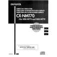 $4.99 NSXMT70 AIWA
Owner's Manual Complete owner's manual in digital format. The manual will be available for download as PDF file aft…
|
|
|
> |
|