|
|
|
Categories
|
|
Information
|
|
Featured Product
|
|
|
 |
|
|
There are currently no product reviews.
 ;
Je suis audiophile belge, électronicien et créateur d'enceintes acoustiques.
J'ai apprécié la qualité des documents fournis. Ils sont très lisibles, ils peuvent être agrandis sans problème et ils sont complets. Pour moi, c'est parfait. Pour cette qualité, je suis d'accord de payer. Et le système de paiement et d'envoi est simple. Merci, continuez comme cela.
Frédéric
;
The cover page was a little scary, very dark but readable. The remainder of the document was better copy and easily readable. Why would I give 5 Stars? (1) PRICE, (2) AUTHENTICITY, It was the real deal, filled with service information, including the specific information I required. (3) PRIVACY, I didn't start to get slammed with spam. (4) EASY TRANSACTION. Painless. (5) COMPLETE, I have found several manuals here, that I could find nowhere else. (6) I will be a repeat customer!
;
Well done!!! I found what I need to have, indeed!
Furthermore, due to my hobby is repairing vintage equipments, I added this web site in my desk toolbar because I have in mind to search further service manuals. Thanks a lot www.owner-manuals.com !
Regards, Maurizio
;
Again very good service manual, this time very fast download. AAAAA+
;
Ckear manual, well reproduced with plenty of overlap on critical pages.
B FRONT C.B
18
D981
<HA>
D984
<HR>
FL901
TP11 IC901 L951
3 0 1
+ C913
GND TP11 (KEY-SCAN) (GND) < CR NETWORK FILTER > 10µF 10µF 1k� 1SS133 1k� 0.1µF 47k� TO FREQUENCY COUNTER
D DECK C.B<HA>
SFR1 12
D DECK C.B<HR>
SFR1 12
DECK�1 P HEAD<HA> DECK�2 R/P/E HEAD
FWD
13
DECK�1 P HEAD<HR>
FWD
13
REV
13
REV
13
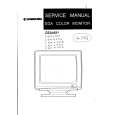
< DECK SECTION >
12. Tape Speed Adjustment (DECK 2) Settings : � Test tape : TTA�100 � Test point : TP8(Lch), TP9(Rch) � Adjustment location : SFR1 Method : Play back the test tape and adjust SFR1 so that the frequency counter reads 3000Hz ± 5Hz (FWD) and FWD SPEED ± 45Hz (REV). 13. Head Azimuth Adjustment (DECK 1, DECK 2) Settings : � Test tape : TTA�330 � Test point : TP8(Lch), TP9(Rch) � Adjustment location : Azimuth adjustment screw Method : Play back (FWD) the 8kHz signal of the test tape and adjust screw so that the output becomes maximum. Next, perform on REV PLAY mode. 14. PB Frequency Response Check (DECK 1, DECK 2) Settings : � Test tape : TTA�330 � Test point :TP8(Lch), TP9(Rch) Method : Play back the 315Hz and 8kHz signals of the test tape and check that the output ratio of the 8kHz signal with respect to that of the 315Hz signal is within 5.0dB. 15. PB Sensitivity Check (DECK 1, DECK 2) Settings : � Test tape : TTA�200 � Test point : TP8(Lch), TP9(Rch) Method : Play back the test tape and check that the output level of the test point is 110mV ± 3.0dB. 16. REC/PB Frequency Response Adjustment (DECK 2) Settings : � Test tape : TTA�602 � Test point : TP8(Lch), TP9(Rch) � Input signal : 1kHz / 8kHz (LINE IN) � Adjustment location : SFR451 (Lch) SFR452 (Rch) Method : Apply a 1kHz signal and REC mode. Then adjust OSC attenuator so that the output level at the TP8, TP9 becomes -20VU (-26dBV). Record and play back the 1kHz and 8kHz signals and adjust SFRs so that the output of the 8kHz signals becomes 1.5dB ± 0.5dB with respect to that of the 1kHz signal. 17. REC/PB Sensitivity Check (DECK 2) Settings : � Test tape : TTA�602 � Test point : TP8(Lch), TP9(Rch) � Input signal : 1kHz (LINE IN) Method : Apply a 1kHz signal and REC mode. Then adjust OSC attenuator so that the output level at TP8, TP9 becomes 0VU (-6dBV). Record and play back the 1kHz signals and check that the output is -1dB ± 3.5dB.
< FRONT SECTION >
18. µ-con OSC Adjustment Settings : � Test point : TP11(KEY-SCAN), GND � Adjustment location : L951 Method : Connect a frequency counter across TP11 and GND via a CR network filter. Then adjust L951 so that the test point becomes 184.94Hz ± 0.18Hz.
� 21 �
|
|
|
> |
|