|
|
|
Categories
|
|
Information
|
|
Featured Product
|
|
|
 |
|
|
There are currently no product reviews.
 ;
Manual was just as described!!! I odered it and in less than a day was able to download it and the text was clear and pages were all complete just as the original manual was. Purcashed this for a friend and they were more than happy. Perfect all around!
 ;
Excellent service and prompt delivery. But it's not a manual - only 4 pages wiring diagrams.
Thanks.
;
The manual I purchased was exactly what I needed to repair my Toshica television. The manual contained schematics and troubleshooting information that was very helpful.
;
Il download del Service Manual JVC HR 4100 non é stato eseguito
;
The Service Manual was just as expected, complete with schematics and I was able to download it in less than an hour after I ordered it. The only problem with these is that the schematics are hard to read due to the small font. I could remedy this by printing them on a larger printer.
9. DC Balance / Mono Distortion Adjustment Settings : � Test point : TP3, TP4 (DC Balance) : TP5(Lch), TP6(Rch) (Distortion) � Adjustment location : L801 � Input level : 60dBµV Method : Set to FM 98.0MHz and adjust L801 so that the voltage between TP3 and TP4 is 0V ± 300mV with minimum distortion.
15. REC/PB Sensitivity Check (DECK 2) Settings : � Test tape : TTA�602 � Test point : TP7(Lch), TP8(Rch) � Input signal : 1kHz (LINE IN) Method : Apply a 1kHz signal and REC mode. Then adjust OSC attenuator so that the output level at TP7, TP8 becomes 280mV. Record and play back the 1kHz signals and check that the output is �1dB ± 3.0dB.
< DECK SECTION >
10. Tape Speed Adjustment (DECK 2) Settings : � Test tape : TTA�100 � Test point : TP7(Lch), TP8(Rch) � Adjustment location : SFR1 Method : Play back the test tape and adjust SFR1 so that the frequency counter reads 3000Hz ± 5Hz (FWD) and ± 45Hz (REV) with respect to forward speed. 11. Head Azimuth Adjustment (DECK 1, DECK 2) Settings : � Test tape : TTA�300 � Test point : TP7(Lch), TP8(Rch) � Adjustment location : Head azimuth adjustment screw Method : Play back (FWD) the 10kHz signal of the test tape and adjust screw so that the output becomes maximum. Next, perform on REV PLAY mode. 12. PB Frequency Response Check (DECK 1, DECK 2) Settings : � Test tape : TTA�300 � Test point :TP7(Lch), TP8(Rch) Method : Play back the 315Hz and 10kHz signals of the test tape and check that the output ratio of the 10kHz signal with respect to that of the 315Hz signal is 0dB ± 3dB. 13. PB Sensitivity Check (DECK 1, DECK 2) Settings : � Test tape : TTA�200 � Test point : TP7(Lch), TP8(Rch) Method : Play back the test tape and check that the output level of the test point is 280mV ± 3dB. 14. REC/PB Frequency Response Adjustment (DECK 2) Settings : � Test tape : TTA�602 � Test point : TP7(Lch), TP8(Rch) � Input signal : 1kHz / 10kHz (LINE IN) � Adjustment location : SFR351 (Lch) SFR352 (Rch) Method : Apply a 1kHz signal and REC mode. Then adjust OSC attenuator so that the output level at the TP7, TP8 becomes 28mV. Record and play back the 1kHz and 10kHz signals and adjust SFRs so that the output of the 10kHz signals becomes 0dB ± 1.0dB with respect to that of the 1kHz signal.
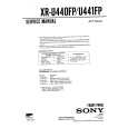
< FRONT SECTION >
B FRONT C.B
FL201
IC101
TP10(GND) L101
TP9
1
1. µ-CON OSC Adjustment Settings : � Test point : TP9 and TP10 (GND) � Adjustment location : L101 Method : Insert AC plug while pressing TUNER function key. Adjust L101 so that the frequency at the test point is 208.80Hz ± 0.2Hz.
� 35 �
|
|
|
> |
|