|
|
|
Categories
|
|
Information
|
|
Featured Product
|
|
|
 |
|
|
There are currently no product reviews.
 ;
factory technician level - complete with board views :
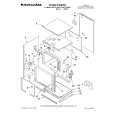
( removing chassis from cabinet , only thing missing ) ;
on weekends , staff is not available so - be patient .
;
Good complete Service-Manual (SONY PVM6041QM)
A few graphics and waveforms not very clear! (-1*)
 ;
Excellent manual. In addition to the information I needed was a complete description of both electronic and mechanical devices.
Excellent site.
Thank you very much.
;
very good and complete manual , it is in english and german is perfect for repair.
;
This manual is complete and of high quality. I am very pleased with the purchase.
Note:
The tape material itself is the same in both types.
2.4. SELF-DIAGNOSIS RESULT DISPLAY
The "SELF-DIAGNOSIS RESULT DISPLAY & MEMORY function is built in this VTR. It means that when the VCR detects undesirable condition, it can be displayed a �Error code (Two numbers from the left)� with Service Mode 2. Since the "Error code" is stored in the EEPROM, it can be displayed although after disconnected the AC leads. It can be displayed with Service Mode 2. (If a second error had been detected, only the most recent error is displayed. ) For more details, refer to the Service Manual for Z-Mechanism Chassis Order number VRD9612M129.
INDICATION CAUSE 01 After cylinder lock is detected, the cylinder does not start rotating again even after tape unloading. 02 Cassette tape is not wound up during the tape unloading except EJECT mode. 03 Mechanism locks during mode transition except EJECT mode. 04 06 07 Mechanism locks during tape unloading. Mechanism locks after tape unloading in EJECT mode. During recording mode, recording signal is less than the normal condition. Recording circuit works except recording mode. Cylinder lock detection. Supply reel mechanism lock detection Take-up reel mechanism lock detection PG shifter automatic adjustment error.
REMEDY/CHECK Check the cylinder motor drive circuit. Check the capstan motor drive circuit.
1. Check the loading motor drive circuit. 2. Check the mechanism phase alignment. 3. Check the mode switch. 1. Check the loading motor drive circuit. 2. Check the mechanism phase alignment. 1. Check the loading motor drive circuit. 2. Check the mechanism phase alignment for cassette holder un
08 16 17 18 2*
Protection of the over-current flowing in transis which produces the power supply for recording mode. Check the recording circuit. Check the cylinder unit and the cylinder motor drive circuit. Check the supply reel mechanism and the sup reel circuit. Check the Take-up reel mechanism and the Take-up reel circuit. Check the servo/system control circuit and the cylinder unit.
Fig. T1 Self-Test indication Display
2.5. CAUTION FOR AC MAINS LEAD (NV-FJ620B/BL)
http://cxema.ru
|
|
|
> |
|