|
There are currently no product reviews.
 ;
Great manual just what I needed, great service as always, thanks.
;
Great quality complete service manual! complete parts list and drawings. Thanks!
;
Great quality complete service manual! complete parts list and drawings. Thanks!
;
Very good quality, prompt response. This website has reasonable prices and wide range of manuals that are hard to find.
;
The document was usefull, and it was exactly what I was looking for.
NX-HD10R
Removing the TRAMECHA Assembly (Refer to Figs. 6 to 9.)
Remove the CL. base assembly and tray. Reference: The TRAMECHA assembly can be removed without removal of the mechanism P.C. board. 1. If the TRAMECHA assembly is lowered and it is TRAMECHA located out of the PLAY position, turn the idle gear assembly in the arrow-marked direction so that the hole in the part f of the tray gear meets the hole on the CL. base assembly. (Set the TRAMECHA assembly at the PLAY position.) 2. Remove the three screws B fastening the TRAMECHA assembly and then remove the TRAMECHA assembly upwards from the front side.
3. At the same time, remove the spring from the groove of the CH. base assembly in the part g of the TRAMECHA assembly. Part g Idle gear
B
B
Tray gear
B
Fig. 6
Tray gear
Note: When reinstalling the TRAMECHA assembly: Check to see if the spring is properly engaged with groove of the CH. base assembly in the part g of the TRAMECHA assembly. After making sure that the three insulators of the TRAMECHA assembly are properly set on the bosses of the L. base assembly's guide, fasten them with the screws.
Part f
L. base assembly
Fig. 7
Spring Part g
Fig. 8
Spring
Groove of CH. base assembly
Fig. 9
1-16
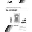 $4.99 NX-HD10R JVC
Owner's Manual Complete owner's manual in digital format. The manual will be available for download as PDF file aft…
|