|
|
|
Categories
|
|
Information
|
|
Featured Product
|
|
|
 |
|
|
There are currently no product reviews.
 ;
It was very usefull, it is clear the quality is super, the price I paid is very afordable.
Generally speaking Iam very happy with this company.
;
The manual was exactly what I needed, Good quality scans too. superb.
;
I am so happy found this site as it consists of so many Manuls and easy to aquire. This onei s exactly what I wanted and much more as it has info on not only how to use the tuner but how to repair it as well. I will come here 1st before purchasing else where! Thanks owner-manual.com!
;
Top class product, I printed it out on A3 paper and it is clear and very easy to follow.
Cheaper than buying a new radio!
;
is part of the manual is very useful for repairing
Here are circuit diagrams
if there is damage, I recommend using this part of the
a complete list of circuit boards and components
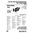
Remove three screws 9 which are holding the guide R (2nd) assy 0 to the bottom plate A. Remove the screw B which is keeping the rear cover C and guide R (2nd) assy 0. Remove the guide R (2nd) assy 0. (7) Remove the protect (M) D, guide bracket E, planet gears F and planet gear bracket G. (8) Remove the E-ring H which is keeping the sheet link I on the guide R (2nd) assy 0, and pull out the hinge stand J. (9) Remove three remaining screws K which are keeping the motor on the motor bracket L, and remove the connector off the Stepping Motor M. (10) Remove two screws N on the Stepping Motor M.
(6)
Detail A
0
I
C
J
K
Q
P
OH N
Note : The guide bracket E must be attached as shown in the following illustration:
No jutting of the gear shaft G is allowed into the oval hole E. Turn
C
L M B E F G
E clockwise for screw C
looseness to affix firmly.
A E 9
The upper plate 3 must be attached as shown in the following illustration.
3
0
9
41154001TH Rev.2
160 /
|
|
|
> |
|