|
|
|
Categories
|
|
Information
|
|
Featured Product
|
|
|
 |
|
|
There are currently no product reviews.
 ;
I was very glad recieving the service manal from You. Additionaly very fast. Extremaly nice servicing. Thanks very mach! Now my GX-220 working better, than it was made. Alexander from Moscow, Russia/
;
Sweet! I won the item on eBay and couldn't adjust the geometry or even keep a steady picure. This guide has the full schematics (not available anywhere else as far as I could tell), and was a bargain for the wealth of knowledge it contains. I hooked it up to my testing equipment, tweaked a few potentiometers and got it playing videogames in no time. Thanks!
;
It was just what I need to fix my old BMW's CD player. Very convenient also. Thank you.
;
Great Manual! It contains all the wiring schematics and mechanical exploded views that are essential for service and repair. I was surprised I even found this for such an old machine. Only wish I knew of this site many years ago.
;
Great manual very clear copied. You are making an incredible job. I appreciate a lot the rapidity and your efficiency. Thanks a lot
D
C G
A
I
H
GND B E
F
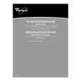
A B Power ON 9.65 VAC 10.52V
Plug out 0 0
C 5.76V
0
D 10.45V
0
E 0.78V
0
F 0.12V
4.13V
G Pulse
0
H 5.07V
4.30V
I -23.9V
0
Voltage level is measured at the following condition. 1. Plug the power cord in AC outlet. 2. Mode switch position : REG, display 0.00 3. Put in the memory protection batteries. 4. Plug out : Plug out the power cord , the memory protection batteries in.
6-2. Reset circuit
VDD
S-80728AN
When the voltage level at the pin No.17 of CPU is not stable, CPU does not work properly. To make a stable voltage, the reset IC(S-80728AN) is used for this circuit. In case the voltage level of VDD becomes down output terminof reset IC is out the stable voltage.
GND
RESET
Pin No.17
�5�
|
|
|
> |
|