|
|
|
Categories
|
|
Information
|
|
Featured Product
|
|
|
 |
|
|
There are currently no product reviews.
 ;
I have never bought a service manual which is as competely readable as this althogh it was a scanned pdf. Thank you for this succesful manual also cheaper than other sites.
;
Thanks for a very good and readable servicemanual. Just what I needed as a "dinosaur technician". I really recommmend this site and will come back.
Åsbjörn
;
The manual I purchased was just what I needed. I was glad to find a site where I can find so many manuals on a wide variety of products.
;
The best diagram that I used in a long time. Everything was right on te money. It was easy and fast. Iwoiuld but again when I need a service manual.
;
The manual is great help for me, i'm happy to have it,thanks
PD-35D30ES
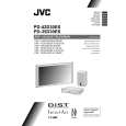
2.4 DISASSEMBLY PROCEDURE [DISPLAY UNIT] CAUTION: � When exchanging parts etc. with the front side (PDP side) facing down, please place a protection sheet below before starting, so as to prevent scratches on the front side. 2.4.1 REMOVING THE REAR COVER (Fig.1) (1) Remove the power cord / system cable / speaker cord. (2) Remove the 14 screws [A] and the 6 screws [B], and remove the REAR COVER. (3) Remove the 1 screw [C], and remove the INSULATION SHEET.
E D
(x2) (x6)
F
(x2)
TERMINAL COVER SPEAKER TERMINAL PWB
AC INLET COVER
A
(x4) (x8)
A
B
(x2)
A
(x2)
G
B
(x4)
REAR COVER
Fig.2 2.4.4 REMOVING THE LINE FILTER PWB (Fig.3) � Remove the REAR COVER. � Remove the AC INLET COVER. (1) Remove the 6 screws [H], and remove the LINE FILTER PWB together with the FILTER SHIELD. NOTE: � Disconnect the connector [CN00P] from the LINE FILTER PWB. � It is advisable to take note of the connecting location (connector number) of the removed connectors. 2.4.5 REMOVING THE AUDIO PWB (Fig.3) � Remove the REAR COVER. � Remove the TERMINAL COVER and SPEAKER TERMINAL PWB. (1) Remove the 4 screws [I], and remove the AUDIO PWB. NOTE: � Disconnect the connectors [CN60SP], [CN600K], [CN60CA], [CN60CE], [CN60CF] from the AUDIO PWB. � It is advisable to take note of the connecting location (connector number) of the removed connectors.
C
INSULATION SHEET
Fig.1 2.4.2 REMOVING THE SPEAKER TERMINAL PWB (Fig.2) � Remove the REAR COVER. (1) Remove the 2 screws [D], and withdraw the TERMINAL COVER. (2) Remove the 6 screws [E], and remove the SPEAKER TERMINAL PWB. NOTE: � Disconnect the connector [CN60SP] from the SPEAKER TERMINAL PWB. � It is advisable to take note of the connecting location (connector number) of the removed connectors. 2.4.3 REMOVING THE AC INLET COVER (Fig.2) � Remove the REAR COVER. (1) Remove the 2 screws [F] and 1 screw [G], and withdraw the AC INLET COVER. NOTE: � Disconnect the connector [CN0PW] from the LINE FILTER PWB. � It is advisable to take note of the connecting location (connector number) of the removed connectors.
2.4.6 REMOVING THE SYSTEM POWER PWB (Fig.3) � Remove the REAR COVER. � Remove the INSULATION SHEET. (1) Remove the 4 screws [J], and remove the SYSTEM POWER PWB. NOTE: � Disconnect the connectors [CN900J], [CN900P], [CN90CB], [CN90CA], [CN900K] from the SYSTEM POWER PWB. � It is advisable to take note of the connecting location (connector number) of the removed connectors.
www.manualscenter.com
(No.52091)1-11
|
|
|
> |
|