|
|
|
Categories
|
|
Information
|
|
Featured Product
|
|
|
 |
|
|
There are currently no product reviews.
 ;
The service manual is really great - thanks to it I was able to install the laser unit and thus "save" my CD-player, which seemed to be impossible before I had the manual.
;
Downloaded the Service manual OK of the Technics Piano and have now repaired it and its going fine. Excellant; thank you for the fine servce. A.M
 ;
This site is working fine! Did buy a manual for SX-EX25L and after a while I could download it and fix the problem. Nice and easy!
;
Complete manual as pdf-file in very good quality. Very helpful and fast availability.
;
Complete service manual in very good scanning quality with all schematic and PWB graphics as well as assembly & maintenance instructions. A slight drawback is that the rastering of the PWB graphics sometimes makes it a bit difficult to follow fine traces, but no showstopper.
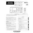
PD-F407
1. SAFETY INFORMATION
This service manual is intended for qualified service technicians; it is not meant for the casual do-it-yourselfer. Qualified technicians have the necessary test equipment and tools, and have been trained to properly and safely repair complex products such as those covered by this manual. Improperly performed repairs can adversely affect the safety and reliability of the product and may void the warranty. If you are not qualified to perform the repair of this product properly and safely, you should not risk trying to do so and refer the repair to a qualified service technician.
IMPORTANT THIS PIONNER APPARATUS CONTAINS LASER OF CLASS 1. SERVICING OPERATION OF THE APPARATUS SHOULD BE DONE BY A SPECIALLY INSTRUCTED PERSON.
LASER DIODE CHARACTERISTICS MAXIMUM OUTPUT POWER : 5 mw WAVELENGTH : 780-785 nm
LABEL CHECK For (PD-F407/WPWXJ only)
Additional Laser Caution
1. Laser Interlock Mechanism The position of the switch (S651) for detecting loading state is detected by the system microprocessor, and the design prevents laser diode oscillation when the switch (S651) is not on CLMP terminal side (CLMP signal is OFF or high level). Thus, the interlock will no longer function if the switch (S651) is deliberatery set to CLMP terminal side. (low level) The interlock also does not function in the test mode V. Laser diode oscillation will continue, if pin 33 of CXA1782CQ (IC151) on the MOTHER BOARD ASSY is connected to GND, or pin 26 of IC351 (LDON) is connected to low level (ON), or else the terminals of Q151 are shorted to each other (fault condition).
AR RE
2. When the cover is opened, close viewing of the objective lens with the naked eye will cause exposure to a Class 1 laser beam. V : Refer to page 25. on the service manual RRV1877.
2
|
|
|
> |
|