|
There are currently no product reviews.
 ;
This service Manual for my JVC AV29BF10EES is very helful. Everything is show in detailed diagrams!!!! If you need really good source of information for this type JVC you are on the right place. I am satisfied and very glad for this excellent book. Thank you.
;
Great service, great value like always!!!
Some of the writing is a bit blur but all is usable.
A+++++++++++++++++
;
Great service manua!
Always great value and fast service A++++++++++++++++++
;
Excellent Service manual, good quality scans, quick service and very good value. Well reccomended ! All good.
;
Great value service manual!
Good-quality scans. Detailed and valuable informations.
A+++++++++++++++
1
2
3
4
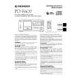
PD-F607, PD-F507 PCB DIAGRAMS
A
NOTE FOR PCB DIAGRAMS:
1. Part numbers in PCB diagrams match those in the schematic diagrams. 2. A comparison between the main parts of PCB and schematic diagrams is shown below.
Symbol in PCB Diagrams Symbol in Schematic Diagrams Part Name
K
HEADPHONE BOARD ASSY
B BCE B BCE
C
EB
C
E Transistor
C
EB
C
E Transistor with resistor
SIDE A
D DGS
G
SD
G
S Field effect transistor
Resistor array 3-terminal regulator
B
3. The parts mounted on this PCB include all necessary parts for several destination. For further information for respective destinations, be sure to check with the schematic diagram.
4. Viewpoint of PCB diagrams
Connector Capacitor
(PNP1439-A)
SIDE A
P. C. Board
Chip Part
SIDE B
J
CN401
C
D
10
K
1 2 3 4
|