|
|
|
Categories
|
|
Information
|
|
Featured Product
|
|
|
 |
|
|
There are currently no product reviews.
 ;
Excellent quality on these manuals. Same as having the original printed manual and incredibly useful when doing a custom install like me. Keep it up on the good work.
 ;
This is an excellent information source. Great quality and tons of info regarding technical service for the Technics SH8065.
;
5 stars on this manual since it is the complete version, not the half manual you find free for download all over the web. Good job.
;
Thank you very much you are helping me a lot with my preferred hobby!!! this manual of an old TV is going to be very helpful!!!!
You are very honest competent great job very clear and well done!!!!
Matteo
;
An excellent service manual contains dismantling locations of components, electronic adjustments,worth the money.
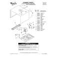
PD-F958, PD-F908
REMOVING THE SERVO MECHANISM ASSY GM
1
Turn gear pulley (B) and position Arm A2 as shown below.
6 7
Remove the connector ASSY (4P) from the float base.
Arm A2 45
Remove the float spring. (To install this part, line up the float angle side of the Servo Mechanism ASSY GM first, and press down on the float base side.)
Float Base
1 Turn
Gear Pulley(B)
7 Remove
Float Spring
Servo Stopper S
2
2 6 2
Float Angle Connector Assy(4P)
8 3 5
Slide the float base in the direction of the arrow 4 while pressing down on the loading base hook, and, lifting it gently, pull it out in the direction of the arrow 5 .
Remove the float rubber from the Servo Mechanism ASSY GM. At this time the float rubber should remain on the float base side. (To install it on the float base when it has been removed, push it into place with a thin cylindrical object.
Servo Mechanism Assy Gm
Float Rubber
5 Remove
Flloat Base
4 Move
Float Base
3
Push Hook Loading Base
45
|
|
|
> |
|