|
|
|
Categories
|
|
Information
|
|
Featured Product
|
|
|
 |
|
|
There are currently no product reviews.
 ;
Superb rendition. Drawings (schematics) complete and unabridged. I do a great deal of vintage audio restoration. Documentation is essential for successful repairs. I have found sources over the years that offer good documentation, but rarely all that is necessary. Owner's Manuals has filled that void with complete and legible documentation. They have narrowed my "favorites" to a more manageable collection. This Denon manual in particular contained the latest revisions level, and offered alterations favorable to updating the item. The Illustrated Parts Breakdown (IPB) was well enough detailed to simplify part symbols and physical locations. You will not be disappointed!
;
Clear and concise. Saved me a lot of time and money.
;
Superb manual. Exactly what I ordered and made available in a very timely manner.
 ;
very fast detailed and accurate hope to do business again
;
This was precisely what I was looking for. Complete and good quality!
5
6
7
8
A
A
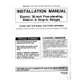
Turn the main power on with the cable to the CN2401 or CN2301 disconnected. Check if 5 V DC is output from Pin 8 of CN2301. YES NO Failure in the CN2301 or LED PWB (failure in the M5V line at Pin 8 of the CN2401)
Turn the main power on with the cable to the CN2302 or CN9010 disconnected. Check if 5 V DC is output from Pin 20 of CN9010. YES NO Is 5 V DC output from Pin 5 of IC9502? NO Failure in the MAIN PWB (failure in the IC9502) Failure in the CN2302 or COMM SLOT IF PWB (failure in the M5V line at Pin 20 of the CN2302)
B
YES Turn the main power on with the COMM SLOT Assy disconnected from CN2303. Check if 3.3 V DC is output from Pin 118 of CN2303.
C
YES NO
Failure in the COMM SLOT Assy (failure in the M3.3V line at Pin 118 of the CN2303)
Turn the main power on with the cable to the CN2302 or CN9010 disconnected. Check if 3.3 V DC is output from Pin 16 of CN9010. YES NO Turn the main power on with the cable to the CN4004 or CN5301 disconnected. Check if 3.3 V DC is output from Pin 50 of CN5301. YES NO Failure in the CN4004 or COMM SLOT IF PWB (failure in the M3.3V line at Pin 1 of the CN4004) Failure in the CN2302 or COMM SLOT IF PWB (failure in the M3.3V line at Pin 16 of the CN2302)
D
Turn the main power on with the cable to the CN2201 or CN9011 disconnected. Check if 3.3 V DC is output from Pin 1 of CN9011. YES NO Is 3.3 V DC output from Pin 4 of IC9503? YES Is 0 V DC output from Pin 14 of CN8502 (AD2)? NO (4.7V) Failure in the AD2 connector or MAIN PWB (failure in IC9501 or X9501) Note: If IC9501 is in failure, replace the whole board. NO Failure in the MAIN PWB (failure in the IC9503)
E
Failure in the CN2201 or KEY PWB (failure in the M3.3V line at Pin 1 of the CN9011)
YES Failure in the MAIN PWB (failure in IC9501 or X9501) Note: If IC9501 is in failure, replace the whole board.
F
PDP-425CMX
5 6 7 8
139
|
|
|
> |
|