|
|
|
Categories
|
|
Information
|
|
Featured Product
|
|
|
 |
|
|
There are currently no product reviews.
 ;
The TEAC A-1500's Service Manual was instrumental in reviving this classic reel-to-reel. Not only does it have the schematics, exploded parts diagram and parts list, it also provided mechanical adjustment information that approximate factory default settings.
 ;
This service manual was determinant to enable to fix my Alpine Amplifier. I am pleased with my purchase. For a 5 star rating I would like to see a higher resolution scan of the printed circuit board lay-out because the gray scale grafics was dificult to see. Also some schematic diagrams were scanned at a slight angle. Never the less, it had all information I needed to troubleshoot and service my equipment.
;
Complete manual, the good quality of reproduction allows enlarged print-out of the schematic diagram in the size it probably had in the original print edition and which is necessary for practical use.
;
The service manual was complete and the components on the drawings very good visible.
;
downloaded next day , manual is very helpful , fast and easy
1
2
3
4
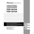
5.1.5 FLOWCHART OF FAILURE ANALYSIS FOR THE MAIN ASSY
A
Flowchart of Failure Analysis for The MAIN Assy
Failure analysis for the MAIN Assy. � MA1
The STB LED does not light although STB 3.3 V power is supplied.
Is the M1 connector securely connected? Yes
No
Securely connect the M1 connector.
B
Is the cable that is connected to the M1 connector broken? No Is resetting of the IF microcomputer canceled? Yes Is the voltage at Pin 1 of the M5 connector high? Yes Is the M5 connector securely connected?
Yes
Replace the cable (J207).
No
Replace the MAIN Assy.
Failure in the RST IC (IC4801) output or its peripheral circuits
No
Replace the MAIN Assy.
Failure in the line between the IF microcomputer and M7 connector
No
Securely connect the M5 connector.
C
Yes Is the cable that is connected to the M5 connector broken? No No problem with the MAIN Assy. Check the LED Assy. Yes Replace the cable (J113).
Failure analysis for the MAIN Assy. � MA2
D
The RELAY port does not work. The power is not turned on.
Is voltage at REQ_IF (3.3 V) on the MAIN Assy high? Yes
No
Can the unit be turned on, using the remote control unit? Yes
No
Can the unit be turned on, using No the Power switch on the main unit? Yes
Replace the cable that connects the SIDE KEY and MAIN Assys. NG Replace the MAIN Assy. NG
Replace the cable that connects the LED IR and MAIN Assys.
NG Replace the cable that connects the LED IR and MAIN Assys. NG
E
Can the unit be turned on, using No the Power switch on the main unit? Yes Replace the cable that connects the SIDE KEY and MAIN Assys.
Replace the LED IR Assy.
NG Replace the cable that connects the SIDE KEY and MAIN Assys. NG Replace the SIDE KEY Assy.
Replace the MAIN Assy. Is the power (1.8 V, 3.3 V) supplied to the main microcomputer? No Replace the MAIN Assy.
� Failure in the REC IC (IC4402) and PM SW (IC4407) outputs � Does the voltage remain low even though it should be active? � A shutdown, indicated by 9 flashes of LED, will be established in 20 seconds.
F
Yes Replace the MAIN Assy.
If the voltage at Pin 129 (RST2 port) on the main microcomputer is high, it is judged that the AC power cord is not plugged in, and operation of the unit will stop there.
82
1 2
PDP-427XD
3 4
|
|
|
> |
|