|
|
|
Categories
|
|
Information
|
|
Featured Product
|
|
|
 |
|
|
There are currently no product reviews.
 ;
thank u so much for this manual that was so cheap that i thought it was a scam but i gambled anyway because it was too good of a deal to pass up and behold,the manual has everything and details of everything even the screws and im still amazed and very happy with my manual .so take my word and jump on it before they realize how cheap they selling thier manuals..thank you so much for taking time to read my thoughts
 ;
I do not have very much to say.
The price is quite covenient, delivery was better as promised (about 12 ours, against the specified 24 hours if I remember well), and the quality of the PDF is more than acceptable.
The Service Manual of Sansui R30 itself is also satisfactory: good graphic for schematics and layouts, simple and well structured.
Giovanni Bianchi
;
Happy to find finally a schematic for this amplifier. The schematic is of good quality, the pcb layout is useless: all is black. Never the less, it is very easy to find the components on the board using the schematics.
;
Hard to find manual was ready the next day. Scans were very legible (including schematics). All the essential parts of the service manual were present (adjustment procedure, schematics, and parts list). It would have been nice if the rest of the manual was included (disassembly procedure, theory of operation, etc.).
;
The Service Manual for the Kenwood KR-V55R provided by owner-manuals.com was as described/advertised. The contents provided the necessary information to effect a diagnosis of the unit. The schematics above all else was instrumental in tracing the the signal flow from component to component.
1
2
3
4
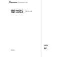
5.1.5 FLOWCHART OF FAILURE ANALYSIS FOR THE MAIN ASSY
A
Flowchart of Failure Analysis for The MAIN Assy
Failure analysis for the MAIN Assy. � MA1
The STB LED does not light although STB 3.3 V power is supplied.
Is the M1 connector securely connected? Yes
No
Securely connect the M1 connector.
B
Is the cable that is connected to the M1 connector broken? No Is resetting of the IF microcomputer canceled? Yes Is the voltage at Pin 1 of the M5 connector high? Yes Is the M5 connector securely connected?
Yes
Replace the cable (J207).
No
Replace the MAIN Assy.
Failure in the RST IC (IC4801) output or its peripheral circuits
No
Replace the MAIN Assy.
Failure in the line between the IF microcomputer and M7 connector
No
Securely connect the M5 connector.
C
Yes Is the cable that is connected to the M5 connector broken? No No problem with the MAIN Assy. Check the LED Assy. Yes Replace the cable (J113).
Failure analysis for the MAIN Assy. � MA2
D
The RELAY port does not work. The power is not turned on.
Is voltage at REQ_IF (3.3 V) on the MAIN Assy high? Yes
No
Can the unit be turned on, using the remote control unit? Yes
No
Can the unit be turned on, using No the Power switch on the main unit? Yes
Replace the cable that connects the SIDE KEY and MAIN Assys. NG Replace the MAIN Assy. NG
Replace the cable that connects the LED IR and MAIN Assys.
NG Replace the cable that connects the LED IR and MAIN Assys. NG
E
Can the unit be turned on, using No the Power switch on the main unit? Yes Replace the cable that connects the SIDE KEY and MAIN Assys.
Replace the LED IR Assy.
NG Replace the cable that connects the SIDE KEY and MAIN Assys. NG Replace the SIDE KEY Assy.
Replace the MAIN Assy. Is the power (1.8 V, 3.3 V) supplied to the main microcomputer? No Replace the MAIN Assy.
� Failure in the REC IC (IC4402) and PM SW (IC4407) outputs � Does the voltage remain low even though it should be active? � A shutdown, indicated by 9 flashes of LED, will be established in 20 seconds.
F
Yes Replace the MAIN Assy.
If the voltage at Pin 129 (RST2 port) on the main microcomputer is high, it is judged that the AC power cord is not plugged in, and operation of the unit will stop there.
82
1 2
PDP-427XD
3 4
|
|
|
> |
|