|
|
|
Categories
|
|
Information
|
|
Featured Product
|
|
|
 |
|
|
There are currently no product reviews.
 ;
Very quick and easy website to use and fast download of manual, quality of manual is excellent and will be pleased to use this service again in the future, thanks so much!
 ;
Easy and secure way to get a complete service manual of a vintage hifi component. Only some parts of the print copy are dificult to read. Nice price!
;
The manual is an excellent reproduction with complete schematics, made troubleshooting and repair a simple process.
;
Up to now you are the BEST! Prompt-efficient and so reasonable ! I have been after SONY service manual for quite some time !Thank you very much ! I can recomend your service to
all my collegagues ! V.Bergfield .
;
This is a very good quality print (scan) of the original SONY service manual. The original from Sony is on very thin paper. Nevertheless it is very clear and sharp and excellent readable. I'm very satisfied to have now this rare document. I've looking for it many years (infrequent). It contains very detailed circuit diagrams, exploded views, part lists, PCB view with good readable connection lines. Very recommended.
1
2
3
4
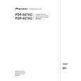
5.1.5 FLOWCHART OF FAILURE ANALYSIS FOR THE MAIN ASSY
A
Flowchart of Failure Analysis for The MAIN Assy
Failure analysis for the MAIN Assy. � MA1
The STB LED does not light although STB 3.3 V power is supplied.
Is the M1 connector securely connected? Yes
No
Securely connect the M1 connector.
B
Is the cable that is connected to the M1 connector broken? No Is resetting of the IF microcomputer canceled? Yes Is the voltage at Pin 1 of the M5 connector high? Yes Is the M5 connector securely connected?
Yes
Replace the cable (J207).
No
Replace the MAIN Assy.
Failure in the RST IC (IC4801) output or its peripheral circuits
No
Replace the MAIN Assy.
Failure in the line between the IF microcomputer and M7 connector
No
Securely connect the M5 connector.
C
Yes Is the cable that is connected to the M5 connector broken? No No problem with the MAIN Assy. Check the LED Assy. Yes Replace the cable (J113).
Failure analysis for the MAIN Assy. � MA2
D
The RELAY port does not work. The power is not turned on.
Is voltage at REQ_IF (3.3 V) on the MAIN Assy high? Yes
No
Can the unit be turned on, using the remote control unit? Yes
No
Can the unit be turned on, using No the Power switch on the main unit? Yes
Replace the cable that connects the SIDE KEY and MAIN Assys. NG Replace the MAIN Assy. NG
Replace the cable that connects the LED IR and MAIN Assys.
NG Replace the cable that connects the LED IR and MAIN Assys. NG
E
Can the unit be turned on, using No the Power switch on the main unit? Yes Replace the cable that connects the SIDE KEY and MAIN Assys.
Replace the LED IR Assy.
NG Replace the cable that connects the SIDE KEY and MAIN Assys. NG Replace the SIDE KEY Assy.
Replace the MAIN Assy. Is the power (1.8 V, 3.3 V) supplied to the main microcomputer? No Replace the MAIN Assy.
� Failure in the REC IC (IC4402) and PM SW (IC4407) outputs � Does the voltage remain low even though it should be active? � A shutdown, indicated by 9 flashes of LED, will be established in 20 seconds.
F
Yes Replace the MAIN Assy.
If the voltage at Pin 129 (RST2 port) on the main microcomputer is high, it is judged that the AC power cord is not plugged in, and operation of the unit will stop there.
82
1 2
PDP-427XD
3 4
|
|
|
> |
|