|
|
|
Categories
|
|
Information
|
|
Featured Product
|
|
|
 |
|
|
There are currently no product reviews.
 ;
have download a number of manuals todate , most are excellant, one or two sometimes a little difficult to read but a least avaialable, great site .
Brad.
;
Excellent had everything I wanted, very happy with purchase
 ;
This service is relatively cheap, document is fast available, schematic is readable.
Thanks.
;
So far I´m a satisfied customer. I have only downloaded "TECHNICS SX-KN470 Service Manual" maybe I will use it later.
Best regards
Peter
;
Good manual. It is complete and of high quality, both text and graphics. The schematics are with the original big size, so it can be viewed or printed without any loss of resulution and sharpness.
5
6
7
8
A
A
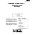
Turn the main power on with the cable to the CN2401 or CN2301 disconnected. Check if 5 V DC is output from Pin 8 of CN2301. YES NO Failure in the CN2301 or LED PWB (failure in the M5V line at Pin 8 of the CN2401)
Turn the main power on with the cable to the CN2302 or CN9010 disconnected. Check if 5 V DC is output from Pin 20 of CN9010. YES NO Is 5 V DC output from Pin 5 of IC9502? NO Failure in the MAIN PWB (failure in the IC9502) Failure in the CN2302 or COMM SLOT IF PWB (failure in the M5V line at Pin 20 of the CN2302)
B
YES Turn the main power on with the COMM SLOT Assy disconnected from CN2303. Check if 3.3 V DC is output from Pin 118 of CN2303.
C
YES NO
Failure in the COMM SLOT Assy (failure in the M3.3V line at Pin 118 of the CN2303)
Turn the main power on with the cable to the CN2302 or CN9010 disconnected. Check if 3.3 V DC is output from Pin 16 of CN9010. YES NO Turn the main power on with the cable to the CN4004 or CN5301 disconnected. Check if 3.3 V DC is output from Pin 50 of CN5301. YES NO Failure in the CN4004 or COMM SLOT IF PWB (failure in the M3.3V line at Pin 1 of the CN4004) Failure in the CN2302 or COMM SLOT IF PWB (failure in the M3.3V line at Pin 16 of the CN2302)
D
Turn the main power on with the cable to the CN2201 or CN9011 disconnected. Check if 3.3 V DC is output from Pin 1 of CN9011. YES NO Is 3.3 V DC output from Pin 4 of IC9503? YES Is 0 V DC output from Pin 14 of CN8502 (AD2)? NO (4.7V) Failure in the AD2 connector or MAIN PWB (failure in IC9501 or X9501) Note: If IC9501 is in failure, replace the whole board. NO Failure in the MAIN PWB (failure in the IC9503)
E
Failure in the CN2201 or KEY PWB (failure in the M3.3V line at Pin 1 of the CN9011)
YES Failure in the MAIN PWB (failure in IC9501 or X9501) Note: If IC9501 is in failure, replace the whole board.
F
PDP-425CMX
5 6 7 8
139
|
|
|
> |
|