|
|
|
Categories
|
|
Information
|
|
Featured Product
|
|
|
 |
|
|
There are currently no product reviews.
 ;
This is an excellent information source. Great quality and tons of info regarding technical service for the Technics SH8065.
;
5 stars on this manual since it is the complete version, not the half manual you find free for download all over the web. Good job.
;
Thank you very much you are helping me a lot with my preferred hobby!!! this manual of an old TV is going to be very helpful!!!!
You are very honest competent great job very clear and well done!!!!
Matteo
;
An excellent service manual contains dismantling locations of components, electronic adjustments,worth the money.
;
Caracteristiques,circuit adjusment,notes on schematis diagram,it's a good service manual,to live well,thanks.
1
2
3
4
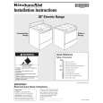
Charged Section
A
High Voltage Generating Point
The places where voltage is 100V or more except for the charged places described above. If the places are touched, there is a risk of electric shock. 1. SW POWER SUPPLY Module ...................................... (215V) 2. X DRIVE Assy ............................................... (�280V to 215V) 3. Y DRIVE Assy ................................................................(345V) 4. SCAN (A) Assy .............................................................. (345V) 5. SCAN (B) Assy .............................................................. (345V) 6. X CONNECTOR (A) Assy ............................ (�280V to 215V) 7. X CONNECTOR (B) Assy ............................ (�280V to 215V)
The places where the commercial AC power is used without passing through the power supply transformer. If the places are touched, there is a risk of electric shock. In addition, the measuring equipment can be damaged if it is connected to the GND of the charged section and the GND of the non-charged section while connecting the set directly to the commercial AC power supply. Therefore, be sure to connect the set via an insulated transformer and supply the current.
B
1. AC Power Cord 2. AC Inlet with Filter 3. Power Switch (S1) 4. Fuse (In the SW POWER SUPPLY Module) 5. STB Transformer and Converter Transformer (In the SW POWER SUPPLY Module) 6. Other primary side of the SW POWER SUPPLY Module
Y DRIVE Assy
C
: Part is Charged Section. : Part is the High Voltage Generating Points other than the Charged Section.
SCAN (A) Assy
Top
SCAN (B) Assy
Front
D
X CONNECTOR (A) Assy
� Remove the IF Earth Metal (No.14 on the page 25)
beforehand when inclines the power supply unit as the right figure.
X DRIVE Assy
X CONNECTOR (B) Assy
E
SW POWER SUPPLY Module AC Inlet with Filter Power Switch (S1)
Power Cord
Fig.1 Charged Section and High Voltage Generating Point (Rear View)
F
4
1 2
PDP-433PU
3 4
|
|
|
> |
|