|
|
|
Categories
|
|
Information
|
|
Featured Product
|
|
|
 |
|
|
There are currently no product reviews.
 ;
Very good copy in a 54 pages PDF archive. This is my sixth purchase here. :)
;
Another excellent buy! File too clear and explanatory.
 ;
A manual hard to find. It was very helpful to restore my device.
;
I am very grateful for this manual. Without it could not repair my receiver.
;
excellent work as always you do cheap, fast net and clean. you do an incredible service......thanks!
1
2
3
4
Charged Section
A
High Voltage Generating Point
The places where voltage is 100V or more except for the charged places described above. If the places are touched, there is a risk of electric shock. 1. POWER SUPPLY Unit................................................... (223V) 2. 50 X DRIVE Assy .......................................... (�230V to 223V) 3. 50 Y DRIVE Assy .......................................................... (353V) 4. 50 SCAN A Assy ............................................................ (353V) 5. 50 SCAN B Assy ............................................................ (353V) 6. X CONNECTOR AAssy ................................ (�230V to 223V) 7. X CONNECTOR B Assy ............................... (�230V to 223V)
The places where the commercial AC power is used without passing through the power supply transformer. If the places are touched, there is a risk of electric shock. In addition, the measuring equipment can be damaged if it is connected to the GND of the charged section and the GND of the non-charged section while connecting the set directly to the commercial AC power supply. Therefore, be sure to connect the set via an insulated transformer and supply the current.
B
1. AC Power Cord 2. AC Inlet with Filter 3. Power Switch (S1) 4. Fuse (In the POWER SUPPLY Unit) 5. STB Transformer and Converter Transformer (In the POWER SUPPLY Unit) 6. Other primary side of the POWER SUPPLY Unit
Discharge the VSUS voltage, as shown below: [Method for discharging the VSUS voltage] 1. Set DRF_SW on the DIGITAL VIDEO Assy to ON (Drive OFF status). *1, 2 2. Leave the switch at that position for about 20-30 seconds. 3. If the power is on, turn it off. Then return DRF_SW to the OFF position. *3 Notes *1: You can also set the unit to "Drive OFF status" by sending the "DRF" RS232C command from the PC. *2: DRF_SW can be switched whether the power is on or off. *3: Power-down will occur if DRF_SW is set to OFF while the power is on. (See "7.1.6 Power on/off function for the largesignal system".)
C
: Part is Charged Section. : Part is the High Voltage Generating Points other than the Charged Section. 50 SCAN B Assy 50 Y DRIVE Assy POWER SUPPLY Unit 50 X DRIVE Assy
D
X CONNECTOR A Assy
E
X CONNECTOR B Assy
50 SCAN A Assy
AC Inlet with Filter
Power Cord
Power Switch (S1)
F
Fig.1 Charged Section and High Voltage Generating Point (Rear View)
4
1 2
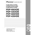
PDP-505PE
3 4
|
|
|
> |
|