|
There are currently no product reviews.
 ;
Good quality for the scan, complete, but as usual for Tascam, not so comprehensive !
 ;
great manual readable & easy to downlaod to be recommanded
;
Very useful, not the best scan, but definitely readable !
;
Complete service manual, good quality scan, great buy !
;
Excellent manual, exactly what I needed! Fair price!
1
2
3
4
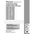
5.1.5 FLOWCHART OF FAILURE ANALYSIS FOR THE MAIN ASSY
A
Flowchart of Failure Analysis for The MAIN Assy
Failure analysis for the MAIN Assy. � MA1
The STB LED does not light although STB 3.3 V power is supplied. No
Failure in the RST IC (IC4801) output or its peripheral circuits
Is resetting of the IF microcomputer canceled? Yes
Replace the MAIN Assy.
B
Is the voltage at Pin 1 of the M5 connector low? Yes Is the M5 connector securely connected? Yes Is the cable that is connected to the M5 connector broken? No No problem with the MAIN Assy. Check the LED Assy.
No
Replace the MAIN Assy.
Failure in the line between the IF microcomputer and M5 connector
No
Securely connect the M5 connector.
Yes
Replace the cable (J113).
C
Failure analysis for the MAIN Assy. � MA2
The RELAY port does not work. The power is not turned on.
D
Is voltage at REQ_IF (3.3 V) on the MAIN Assy high? Yes
No
Can the unit be turned on, using the remote control unit? Yes
No
Replace the cable that connects the LED IR and MAIN Assys.
NG Replace the LED IR Assy.
Can the unit be turned on, using the Power switch on the side key? Yes Can the unit be turned on, using RS-232C commands?
No
Replace the cable that connects the SIDE KEY and MAIN Assys.
NG Replace the SIDE KEY Assy.
NG
Replace the MAIN Assy.
Failure in the RS-232C driver and its peripheral circuits
E
Is the power (1.8 V, 3.3 V) supplied to the main microcomputer? Yes Replace the MAIN Assy.
No
Replace the MAIN Assy.
If the voltage at Pin 129 (RST3 port) on the main microcomputer is high, it is judged that the AC power cord is not plugged in, and operation of the unit will stop there.
F
90
1 2
PDP-5071PU
3 4
|